 Products Home / Optical Elements / Optical Filters / Spectral Filters / UV/VIS Bandpass & Laser Line Filters: 340 - 694.3 nm Center Wavelength
UV/VIS Bandpass & Laser Line Filters: 340 - 694.3 nm Center Wavelength
- Pass Regions Between 1 nm and 40 nm FWHM
- Ø1/2" and Ø1" Mounted Filters
- <0.01% Transmission in Blocking Region
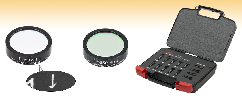
FL532-1
FB650-40
Transmission Direction Indicator
FKB-VIS-40


Please Wait

Please see the Tutorial tab for more information about the structure of the filter and the transmission direction arrow.


Features
- Central Wavelengths from 340 nm to 694.3 nm
- 1, 3, 10, or 40 nm Bandpass Regions
- Ø1/2" or Ø1" Mounted Filters
- Edge Scribed for Superb Long-Term Stability
- Typical Transmission Plots Available for Every Filter
- Laser Line Filters for Popular Laser Diode, Argon, Krypton,
HeCd, HeNe, and Nd:YAG Laser Lines
The bandpass and laser line filters shown on this page feature center wavelengths shorter than 700 nm. Transmission curves for individual filters are available by viewing the Spec sheet for an individual filter. Each filter is mounted in an unthreaded black anodized aluminum ring with an outer diameter of Ø1/2" or Ø1" and a maximum edge thickness of 6.3 mm. Please note that Ø1/2" filter options are highlighted in green in the tables below.
Thorlabs' bandpass filters provide one of the simplest ways to transmit a well-defined wavelength band of light, while rejecting other unwanted radiation. Their design is essentially that of a thin film Fabry-Perot Interferometer formed by vacuum deposition techniques and consists of two reflecting stacks, separated by an even-order spacer layer. These reflecting stacks are constructed from alternating layers of high and low refractive index materials, which can have a reflectance in excess of 99.99%. By varying the thickness of the spacer layer and/or the number of reflecting layers, the central wavelength and bandwidth of the filter can be altered.
This type of filter displays very high transmission in the bandpass region, but the spectral range of blocked light on either side of the bandpass region is narrow. To compensate for this, an additional blocking component is added, which is either an all dielectric or a metal-dielectric depending on the requirements of the filter. Although this additional blocking component will eliminate any unwanted out-of-band radiation, it also reduces the filter's overall transmission throughput. For applications with demanding wavefront requirements, such as imaging, please consider our premium bandpass filters.
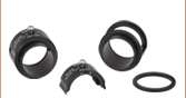
Each filter is housed in a black anodized aluminum ring that is labeled with an arrow indicating the design transmission direction. The ring makes handling easier and enhances the blocking OD by limiting scattering. These filters can be mounted in our extensive line of filter mounts and wheels. As the mounts are not threaded, retaining rings will be required to mount the filters in one of our internally-threaded lens tubes or filter mounts, as shown above. We do not recommend removing the filter from its mount, as the filter consists of several layers of glass that are held together with epoxy and the mounting ring. These glass layers are necessary to protect the dielectric coating from the atmosphere; exposure would significantly reduce the filter's transmission efficiency over time.
Please note that due to the gradual breakdown of the dielectric coatings, our bandpass filters have a typical lifetime of two years. Older filters will experience a decrease in overall transmission in the passband.
| Additional Bandpass Filters | |||||
|---|---|---|---|---|---|
| UV/Visible Bandpass Filters 340 - 694.3 nm CWLs |
NIR Bandpass Filters 700 - 1650 nm CWLs |
MIR Bandpass Filters 1750 - 9500 nm CWLs |
Premium Bandpass Filters 355 - 1550 nm CWLs |
Bandpass Filter Kits | |
| We also offer custom bandpass filters with other central wavelengths or FWHM. To request a quote, contact Tech Support. | |||||
| Common Specifications | |
|---|---|
| Out of Band Transmission | <0.01% |
| Housing Diameter | 1/2" (Laser Line) 1" (Bandpass) |
| Housing Diameter Tolerance | +0.0 / -0.2 mm |
| Clear Aperture | Ø8.6 mm (Min) for Ø1/2" Ø21 mm (Min) for Ø1" |
| Thickness | <6.3 mm |
| Surface/Coating Quality | 80-50 Scratch-Dig |
| Edge Treatment | Mounted in Black Anodized Aluminum Ring |
| Edge Markings | CWL-FWHM ↑ Lot Number; The Arrow Points in the Direction of the light transmission |
| Substrates | Schott Borofloat and Soda Lime |
| Optimum Operating Temperature | 23 °C |
| Operating Temperature | -50 to 80 °C |

Click to Enlarge
The number of layers shown in this schematic is not indicative of the number of layers in an actual bandpass filter. Also the drawing is not to scale.
Bandpass Filter Structure
A bandpass filter is created by depositing layers of material on the surface of the substrate. Typically, there are several dielectric stacks separated by spacer layers. The dielectric stack is composed of a large number of alternating layers of low-index and high-index dielectric material. The thickness of each layer in the dielectric stack is λ/4, where λ is the central wavelength of the bandpass filter (i.e. the wavelength with the highest transmittance through the filter). The spacer layers are placed in between the dielectric stacks and have a thickness of (nλ)/2, where n is an integer. The spacer layers can be formed from colored glass, epoxy, dyes, metallic, or dielectric layers. A Fabry-Perot cavity is formed by each spacer layer sandwiched between dielectric stacks. The filter is mounted in an engraved metal ring for protection and ease of handling.
Filter Operation Overview
The constructive interference conditions of a Fabry-Perot cavity allow light at the central wavelength, and a small band of wavelengths to either side, to be transmitted efficiently, while destructive interference prevents the light outside the passband from being transmitted. However, the band of blocked wavelengths on either side of the central wavelength is small. In order increase the blocking range of the filter, materials with broad blocking ranges are used for or coated onto the spacer layers and the substrate. Although these materials effectively block out of band transmission of incident radiation they also decrease the transmission through the filter in the passband.

FB800-10 and FB800-40 filters were used to make the measurement that resulted in the plot above.
Filter Orientation
An engraved arrow on the edge of the filter is used to indicate the recommended direction for the transmission of light through the filter. Although the filter will function with either side facing the source, it is better to place the coated side toward the source. This will minimize any thermal effects or possible thermal damage that blocking intense out-of-band radiation might cause due to the absorption of the out-of-band radiation by the substrate or colored glass filter layers. The plot to the right was made by illuminating the filter with a low intensity broadband light and measuring the transmission as a function of wavelength. The plot shows that the transmission direction through the filter has very little effect on the intensity and the spectrum of the light transmitted through the filter. The minimal variation between the forward and backward traces is most likely due to a small shift in the incident angle of the light on the filter introduced when the filter was removed, flipped over, and replaced in the jig.
The filter is intended to be used with collimated light normally incident on the surface of the filter. For uncollimated light or light striking the surface and an angle not normally incident to the surface the central wavelength (wavelength corresponding to peak transmission) will shift toward lower wavelengths and the shape of the transmission region (passband) will change. Varying the angle of incidence by a small amount can be used to effectively tune the passband over a narrow range. Large changes in the incident angle will cause larger shifts in the central wavelength but will also significantly distort the shape of the passband and, more importantly, cause a significant decrease in the transmittance of the passband.
Filter Temperature
The central wavelength of the bandpass filter can be tuned slightly (~1 nm over the operating range of the filter) by changing the temperature of the filter. This is primarily due to the slight thermal expansion or contraction of the layers.
| Posted Comments: | |
SUHYUN PARK
(posted 2020-06-29 04:22:38.597) Hello, I am SUHYUN PARK from Gwangju Institiute of Science and Technology, South Korea. I want to use FL355-10 for pulse Nd-YAG laser. But I could not find the damage threshold. Could you let me know? YLohia
(posted 2020-06-29 09:47:17.0) Hello Suhyun, thank you for contacting Thorlabs. Unfortunately, we have not yet performed formal damage threshold testing for these filters. That being said, these filters include layers of epoxy and absorptive glass, and they are not suitable for high power applications. If damage is a concern, we recommend going with our Premium Hard-Coated Bandpass Filters instead. Martin Mickel
(posted 2019-07-09 08:15:26.817) Hi Thorlabs,
is it possible to clean the FL632.8-1 with acetone or something similar?
Best,
Martin YLohia
(posted 2019-07-10 08:53:26.0) Hello Martin, thank you for contacting Thorlabs. Yes, acetone can be used to clean this filter (care must be taken that the acetone does not leak to the edges of the filter). simonini
(posted 2018-09-24 16:47:57.81) Dears,
I would like to know which is the intensity damage threshold for FL514.5-3. I would need to use it for a CW laser which could arrive till 2Watt on a beam of 3mm diameter.
Regards,
Alessia Simonini YLohia
(posted 2018-09-24 12:15:27.0) Dear Alessia, thank you for contacting Thorlabs. Unfortunately, we have not yet performed formal damage threshold testing for these filters. That being said, these filters include layers of epoxy and absorptive glass, and they are not suitable for high power applications. jv
(posted 2017-11-10 11:24:12.633) Many of your bandpass filters have blocking band go out to 3000nm. But others, especially in the 650nm to 900nm, only block to about 1200nm. This means I have to find another filter to block out to 3000nm. Is it not possible to create all filters to block out to 3000nm?
Can you suggest a filter that blocks from 1000nm to 3000nm please?
Thanks
Janis tfrisch
(posted 2018-01-02 03:18:54.0) Hello, thank you for contacting Thorlabs. These filters were not all designed with rejecting so far into the NIR, you are correct. For some wavelengths, it may be suitable to use our NENIR series absorptive filters which have some transmission in visible wavelengths. I will reach out to you directly about what your source is and what wavelengths you need to pass. For applications with a few narrowband sources, it may be suitable to stack bandpass and notch filters. xiazhiwei2002
(posted 2017-09-26 11:13:06.797) Dear Sirs,I noticed that you have added the Size:Φ1/2" otthe Bandpass Filters of some wavelengths, such as 488nm, 514.5nm, 532nm, 632.8nm, 635nm, 780nm, 850nm, 1064nm, 1550nm.I really appreciate your efforts. But it is a pity that the filters of other wavelengths, such as 440nm, 500nm, 680nm, 870nm, 1300nm, 1550nm, 1650nm and so on, are not available in this size(Φ1/2"). Would you like to add the size(Φ1/2") to the filters of this wavelengths? Or even the filters of all wavelengths?
Thanks. nbayconich
(posted 2017-10-05 08:42:07.0) Thank you for contacting Thorlabs. We can provide custom size filters upon request. Please reach out to us at techsupport@thorlabs.com for more information on custom items. kirilowk
(posted 2017-07-18 17:33:21.833) Hello, May I know the intensity damage threshold(LIDT) for your bandpass filters (FB405-10 and FBH405-10)? Thanks tfrisch
(posted 2017-07-27 10:13:45.0) Hello, thank you for contacting Thorlabs. While we do not have a formal damage threshold spec for CW, these filters include layers of epoxy and absorptive glass, and they are not suitable for high power applications. I will reach out to you directly to discuss your source, though the FBH series is an all dielectric construction without absorptive glass or epoxy and would have a higher damage threshold. ronny
(posted 2017-01-10 18:45:28.373) Dear Sirs,
I have a FL532-1 since several years (since 2012) in operation. Sometimes they were stored/operated between -10 and 40 °C. Meanwhile the backside is totally blind. Do you know if the hard-coated filters will have a longer lifetime? tfrisch
(posted 2017-01-11 11:57:22.0) Hello, thank you for contacting thorlabs. I would expect IBS coatings (as on the hard coated filters) to have a longer lifetime than these filters, yes. I will reach out to you directly to discuss this. raul.montero
(posted 2017-01-07 06:22:46.153) Is it posible to have custom interferential filters with bandwidths narrower than those appearing in the online catalog? tfrisch
(posted 2017-01-09 10:11:23.0) Hello, thank you for contacting Thorlabs. I will reach out to you directly about our custom capabilities. jy3796
(posted 2016-05-19 17:41:12.183) Is it possible to have transmission versus wavelength curves for different angles not normally incident to the surface? Interesting would be the curves for 29 bandpass filters. And if possible over the angle of interest from 0 to 90 degrees. Thanks! besembeson
(posted 2016-05-24 11:31:18.0) Response from Bweh at Thorlabs USA: Yes this is possible. We could do such special scans at various angles other than normal incidence but not at 90deg. I have contacted you to follow-up with your requirements. sny
(posted 2016-01-25 11:39:02.58) Dear sirs,
I am interested in purchasing a bandpass filter centered at 325 nm.
According to your online catalog the filter centered at 340 nm is the one with the lowest wavelength.
Do you provide filters at 325 nm? besembeson
(posted 2016-02-01 09:43:32.0) Response from Bweh at Thorlabs USA: We can provide this as a special item for now. We will contact you. thevenard
(posted 2015-01-14 12:27:40.803) Does this filter conserve linear (but non s or p) polarization ?
Thank you very much in advance.
Laura besembeson
(posted 2015-01-22 04:22:58.0) Response from Bweh at Thorlabs USA: We don't expect this to alter the polarization state but there is a chance, however, to create stress induced birefringence when not mounted properly. We would recommend using SM1LTRR to mount the filter for such applications. b.povazay
(posted 2014-07-31 12:10:53.073) I wonder why you do not offer an Hg i-line filter at 365nm, which probably is as significant for UV applications as the 532nm filter for Nd:YAG lasers in the green...
In a mount for the (PM200 powermeter) Si S120VC detection head and a calibration file together with irradiance display this could be a very valuable and probably cost efficient replacement option for existing UV irradiance powermeters in curing, photolithography and other fields. jlow
(posted 2014-08-07 02:59:46.0) Response from Jeremy at Thorlabs: Thank you for the suggestion for the 365nm option. We'll look at this as one of our next additions. asad.hussain
(posted 2013-06-09 08:53:53.68) Would you pls tell me damage threshold for FL514.5-10? Thanks tcohen
(posted 2013-08-05 11:09:00.0) Response from Tim at Thorlabs: We currently have parts in queue to obtain an empirical damage threshold value. In the meantime, please note that these are lower power filters. We would expect the damage threshold to be approximately .05J/cm^2 or less in the pass band. nathan_pust
(posted 2013-05-08 18:25:47.093) For part FL532-1, the transmission data shows only a 25% transmission maximum, while the table on the website quotes 40%. Which one is correct? sharrell
(posted 2013-05-09 17:04:00.0) Response from Sean at Thorlabs: The FL532-1 filter should have a minimum transmission of 40%. Our optics team is working on collecting new filter transmission data which will be posted to the website as soon as it's available. tholste
(posted 2012-08-27 17:30:00.0) Response from Tor at Thorlabs to halverso: Thank you for contacting us -- we do not currently offer these dimensions. I will contact you directly for more details about your application. halverso
(posted 2012-08-27 16:01:53.0) Are these available in either 2" diameter or 2" square unmounted form factors? Thorlabs
(posted 2010-12-06 18:32:38.0) Response from Javier at Thorlabs to Matthias: We currently do not have the Sellmeier coefficients for the substrates of our bandpass filters. However, I will work with our optics department in gathering information about dispersion effects. I will contact you directly for further discussion. matthias.hensen
(posted 2010-12-06 11:12:15.0) Hey! We are using the FB530-10 inside an interferometer. I have to manage the dispersion, so I would like to know if you offer Sellmeier data for your substrates, denoted as "Schott borofloat and soda lime". Best regards! tor
(posted 2010-11-24 08:27:29.0) Response from Tor at Thorlabs to tstier: I have created an Excel file of this filters spectral transmission, and I will send it to you shortly. tstier
(posted 2010-11-23 17:55:18.0) Could you please provide FB650-40 transmission spectrum in excel format? 270-1200nm if possible jjurado
(posted 2010-06-01 14:44:20.0) Response from Javier at Thorlabs to last poster: The filter coating is designed so that only the specified band is transmitted, and the transmission at the rejection range (200-1200nm for the FB450 filter, for example) is kept at a minimum (< 0.01%). As mentioned in the Tutorial section, the constructive interference conditions of a Fabry-Perot cavity allow light at the central wavelength, and a small band of wavelengths to either side, to be transmitted efficiently, while destructive interference prevents the light outside the passband from being transmitted. We can provide sample scans of these filter if you would like. user
(posted 2010-06-01 12:54:07.0) Is there a second order that comes thru? If I use a filter at 450 nm is there light at 900 nm that is transmitted? apalmentieri
(posted 2010-02-19 19:25:56.0) A response from Adam at Thorlabs to Luis: We can provide customer transmission vs. wavelength curves for our customers. I will contact you directly to get information about the wavelength range and AOIs needed. Luis.CerveroGallart
(posted 2010-02-19 09:43:03.0) Is it possible to have transmission versus wavelength curves for different angles not normally incident to the surface? Interesting would be the curves for the FB850-10, FB850-40, FB950-10 and FB950-40 and if possible over the whole angle range from 0 to 90 degrees. Thanks! Luis apalmentieri
(posted 2010-01-27 09:51:43.0) A response from Adam at Thorlabs: To determine the dB for these curves you can use the formula
Attenuation(dB) = 10 * Log(1/%T)
I have already modified curves for the FB500-40 and FES1000 and will send them to you shortly. delaune
(posted 2010-01-26 20:20:33.0) Dear Sir,
Beginner in the optical field, I wish to know the attenuation value (in dB) of the FB500-40 & FES1000 that were purchased some time ago. Is possible to determine this value from the transmission graph shown in the documents&drawings part? Thanks for the answers. apalmentieri
(posted 2010-01-06 09:50:12.0) A response from Adam at Thorlabs to Marc: It is possible to get transmission data files. I will email you direct with some files. mverhaegen
(posted 2010-01-06 08:37:15.0) Is it possible to have transmission data file of one of your FBxxx-10 filter? Whatever central wavelength between 400 and 1000nm.
Thank you,
Marc Verhaegen
CTO, Photon etc. apalmentieri
(posted 2009-11-17 11:11:39.0) A response from Adam at Thorlabs: Michael, I believe we have this data and I will send it to your email address. michael.spurr
(posted 2009-11-17 05:02:23.0) As with the post by mary.breeden, would it be possible to have transmission data for the following filters:
FB405-10
FB420-10
FB440-10
Many thanks, Michael klee
(posted 2009-10-28 13:34:32.0) A response from Ken at Thorlabs to kettle: We may be able to do this but we will need more information. Please send a drawing to techsupport@thorlabs.com so that we can take a look. kettle
(posted 2009-10-27 18:44:18.0) Dear Sir, I am looking for narrow bandpass filters like FB450-10 for underwater applications. It is important that the filter be 1.5-2" square with holes drilled in the corners. Do you carry a product like this or know where I can get one?
Sincerely,
Anthony Kettle klee
(posted 2009-07-13 10:23:29.0) A response from Ken at Thorlabs to SergeyKostrov: The Tutorial can be seen by clicking on the tab within this page. It can not be seen in a separate window/tab. SergeyKostrov
(posted 2009-07-11 14:00:37.0) A Web-Link to Tutorial
http://www.thorlabs.com/1001Tutorial
is broken apalmentieri
(posted 2009-07-09 11:35:32.0) A response from Adam at Thorlabs: Currently, we do not have the transmission information for these filters all the out to 10um. We can only provide experimental scans out to 3um. I will contact you directly to find out more about the information you are looking for. emily.peterson
(posted 2009-07-06 11:37:22.0) I am interested to know the IR transmission of these filters in the 2-10 micron range. I am using the 1650-12 nm filter, as well as 1550, 1450, 1200, 1050. klee
(posted 2009-06-24 11:18:46.0) A response from Ken at Thorlabs to s.obyrne: We do carry 1/2" Laser Line filters for certain wavelengths. You can click on the Laser Line Filters under the Related Products above to get to see what wavelengths we have. If you do not find the wavelength you need, send an email to techsupport@thorlabs.com and we will send you a quote for the custom 1/2" filter(s). s.obyrne
(posted 2009-06-24 05:41:56.0) Are you going to make a 1/2" version of these for use in the 30 mm cage assemblies. You have 1/2" filter holders, but no filters! Tyler
(posted 2008-09-12 15:20:53.0) A response from Tyler at Thorlabs to mary.breeden: A member of the technical support staff will email the data files that you requested. Thank you for using our products. If you have any additional inquires, please let us know. mary.breeden
(posted 2008-09-08 15:03:24.0) I recently purchased the visible (10nm) and IR filter kits. Is it possible to get the transmission data (other than the graphs available in the Drawings & Documents area) so that I can accuratly portray them in Zemax? Any MS Office file format (including 2007) would be suitable.
Thanks!
Mary technicalmarketing
(posted 2008-02-21 15:49:28.0) Thorlabs has not currently tested that bandpass filter in order to determine its damage threshold. Please contact our technical support staff to discuss whether the filter is a feasible choice for your application. ganyi820
(posted 2008-02-18 15:18:31.0) Hello,
May I know the intensity damage threshold for your bandpass filters (FB550-40)?
Thanks |
| Item # | CWLa | FWHMb | T (Min)c | Blockingd | Transmission/ OD Datae |
Laser Line | Size |
|---|---|---|---|---|---|---|---|
| FB340-10 | 340 ± 2 nm | 10 ± 2 nm | 25% | 200 - 3000 nm | N/A | Ø1" | |
| FB350-10 | 350 ± 2 nm | 10 ± 2 nm | 25% | 200 - 3000 nm | N/A | Ø1" | |
| FL355-10 | 355 ± 2 nm | 10 ± 2 nm | 25% | 200 - 1150 nm | Nd:YAG | Ø1" | |
| FB360-10 | 360 ± 2 nm | 10 ± 2 nm | 25% | 200 - 3000 nm | N/A | Ø1" | |
| FB370-10 | 370 ± 2 nm | 10 ± 2 nm | 25% | 200 - 3000 nm | N/A | Ø1" | |
| FB380-10 | 380 ± 2 nm | 10 ± 2 nm | 25% | 200 - 3000 nm | N/A | Ø1" | |
| FB390-10 | 390 ± 2 nm | 10 ± 2 nm | 30% | 200 - 3000 nm | N/A | Ø1" |
- Center Wavelength
- Full Width Half Max
- Minimum Transmission at Center Wavelength
- <0.01% (<-40 dB)
- Click on
 for a plot and downloadable data. Measured data accounts for all losses including Fresnel reflections. Please note that transmission is only guaranteed for the specified center wavelength and that the data in the plots is typical. Performance may vary from lot to lot.
| Item # | CWLa | FWHMb | T (Min)c | Blockingd | Transmission/ OD Datae |
Laser Line | Size |
|---|---|---|---|---|---|---|---|
| FB400-10 | 400 ± 2 nm | 10 ± 2 nm | 37% | 200 - 3000 nm | N/A | Ø1" | |
| FB400-40 | 400 ± 8 nm | 40 ± 8 nm | 45% | 200 - 1150 nm | N/A | Ø1" | |
| FB405-10 | 405 ± 2 nm | 10 ± 2 nm | 37% | 200 - 3000 nm | N/A | Ø1" | |
| FB410-10 | 410 ± 2 nm | 10 ± 2 nm | 40% | 200 - 3000 nm | N/A | Ø1" | |
| FB420-10 | 420 ± 2 nm | 10 ± 2 nm | 45% | 200 - 3000 nm | N/A | Ø1" | |
| FB430-10 | 430 ± 2 nm | 10 ± 2 nm | 45% | 200 - 3000 nm | N/A | Ø1" | |
| FB440-10 | 440 ± 2 nm | 10 ± 2 nm | 45% | 200 - 3000 nm | N/A | Ø1" | |
| FL441.6-10 | 441.6 ± 2 nm | 10 ± 2 nm | 60% | 200 - 1150 nm | HeCd | Ø1" | |
| FB450-10 | 450 ± 2 nm | 10 ± 2 nm | 45% | 200 - 3000 nm | N/A | Ø1" | |
| FB450-40 | 450 ± 8 nm | 40 ± 8 nm | 45% | 200 - 1150 nm | N/A | Ø1" | |
| FL457.9-10 | 457.9 ± 2 nm | 10 ± 2 nm | 65% | 200 - 1150 nm | Argon | Ø1" | |
| FL460-10 | 460 ± 2 nm | 10 ± 2 nm | 65% | 200 - 1150 nm | Argon | Ø1" | |
| FB460-10 | 460 ± 2 nm | 10 ± 2 nm | 45% | 200 - 3000 nm | N/A | Ø1" | |
| FB470-10 | 470 ± 2 nm | 10 ± 2 nm | 45% | 200 - 3000 nm | N/A | Ø1" | |
| FB480-10 | 480 ± 2 nm | 10 ± 2 nm | 45% | 200 - 3000 nm | N/A | Ø1" | |
| FL488-1 | 488 ± 0.2 nm | 1 ± 0.2 nm | 40% | 200 - 1150 nm | Argon | Ø1" | |
| FL488-3 | 488 ± 0.6 nm | 3 ± 0.6 nm | 45% | 200 - 1150 nm | Argon | Ø1" | |
| FL05488-10 | 488 ± 2 nm | 10 ± 2 nm | 65% | 200 - 1100 nm | Argon | Ø1/2" | |
| FL488-10 | 488 ± 2 nm | 10 ± 2 nm | 65% | 200 - 1150 nm | Argon | Ø1" | |
| FB490-10 | 490 ± 2 nm | 10 ± 2 nm | 45% | 200 - 3000 nm | N/A | Ø1" |
- Center Wavelength
- Full Width Half Max
- Minimum Transmission at Center Wavelength
- <0.01% (<-40 dB)
- Click on for a plot and downloadable data. Measured data accounts for all losses including Fresnel reflections. Please note that transmission is only guaranteed for the specified center wavelength and that the data in the plots is typical. Performance may vary from lot to lot.
| Item # | CWLa | FWHMb | T (Min)c | Blockingd | Transmission/ OD Datae |
Laser Line | Size |
|---|---|---|---|---|---|---|---|
| FB500-10 | 500 ± 2 nm | 10 ± 2 nm | 50% | 200 - 1200 nm | N/A | Ø1" | |
| FB500-40 | 500 ± 8 nm | 40 ± 8 nm | 70% | 200 - 1150 nm | N/A | Ø1" | |
| FL508.5-10 | 508.5 ± 2 nm | 10 ± 2 nm | 65% | 200 - 1150 nm | Argon | Ø1" | |
| FB510-10 | 510 ± 2 nm | 10 ± 2 nm | 50% | 200 - 3000 nm | N/A | Ø1" | |
| FL05514.5-1 | 514.5 ± 0.2 nm | 1 ± 0.2 nm | 45% | 200 - 1100 nm | Argon | Ø1/2" | |
| FL514.5-1 | 514.5 ± 0.2 nm | 1 ± 0.2 nm | 45% | 200 - 1150 nm | Argon | Ø1" | |
| FL514.5-3 | 514.5 ± 0.6 nm | 3 ± 0.6 nm | 55% | 200 - 1150 nm | Argon | Ø1" | |
| FL514.5-10 | 514.5 ± 2 nm | 10 ± 2 nm | 65% | 200 - 1150 nm | Argon | Ø1" | |
| FB520-10 | 520 ± 2 nm | 10 ± 2 nm | 50% | 200 - 3000 nm | N/A | Ø1" | |
| FB530-10 | 530 ± 2 nm | 10 ± 2 nm | 50% | 200 - 3000 nm | N/A | Ø1" | |
| FL05532-1 | 532 ± 0.2 nm | 1 ± 0.2 nm | 40% | 200 - 1100 nm | Nd:YAG | Ø1/2" | |
| FL532-1 | 532 ± 0.2 nm | 1 ± 0.2 nm | 40% | 200 - 1150 nm | Nd:YAG | Ø1" | |
| FL532-3 | 532 ± 0.6 nm | 3 ± 0.6 nm | 60% | 200 - 1150 nm | Nd:YAG | Ø1" | |
| FL05532-10 | 532 ± 2 nm | 10 ± 2 nm | 70% | 200 - 1100 nm | Nd:YAG | Ø1/2" | |
| FL532-10 | 532 ± 2 nm | 10 ± 2 nm | 70% | 200 - 1150 nm | Nd:YAG | Ø1" | |
| FB540-10 | 540 ± 2 nm | 10 ± 2 nm | 50% | 200 - 3000 nm | N/A | Ø1" | |
| FL543.5-10 | 543.5 ± 2 nm | 10 ± 2 nm | 70% | 200 - 1150 nm | HeNe | Ø1" | |
| FB550-10 | 550 ± 2 nm | 10 ± 2 nm | 50% | 200 - 1200 nm | N/A | Ø1" | |
| FB550-40 | 550 ± 8 nm | 40 ± 8 nm | 70% | 200 - 1150 nm | N/A | Ø1" | |
| FB560-10 | 560 ± 2 nm | 10 ± 2 nm | 50% | 200 - 3000 nm | N/A | Ø1" | |
| FB570-10 | 570 ± 2 nm | 10 ± 2 nm | 50% | 200 - 3000 nm | N/A | Ø1" | |
| FB580-10 | 580 ± 2 nm | 10 ± 2 nm | 50% | 200 - 3000 nm | N/A | Ø1" | |
| FB590-10 | 590 ± 2 nm | 10 ± 2 nm | 50% | 200 - 3000 nm | N/A | Ø1" |
- Center Wavelength
- Full Width Half Max
- Minimum Transmission at Center Wavelength
- <0.01% (<-40 dB)
- Click on for a plot and downloadable data. Measured data accounts for all losses including Fresnel reflections. Please note that transmission is only guaranteed for the specified center wavelength and that the data in the plots is typical. Performance may vary from lot to lot.
| Item # | CWLa | FWHMb | T (Min)c | Blockingd | Transmission/ OD Datae |
Laser Line | Size |
|---|---|---|---|---|---|---|---|
| FB600-10 | 600 ± 2 nm | 10 ± 2 nm | 50% | 200 - 1200 nm | N/A | Ø1" | |
| FB600-40 | 600 ± 8 nm | 40 ± 8 nm | 70% | 200 - 1150 nm | N/A | Ø1" | |
| FB610-10 | 610 ± 2 nm | 10 ± 2 nm | 50% | 200 - 3000 nm | N/A | Ø1" | |
| FB620-10 | 620 ± 2 nm | 10 ± 2 nm | 50% | 200 - 3000 nm | N/A | Ø1" | |
| FB630-10 | 630 ± 2 nm | 10 ± 2 nm | 50% | 200 - 3000 nm | N/A | Ø1" | |
| FL05632.8-1 | 632.8 ± 0.2 nm | 1 ± 0.2 nm | 50% | 200 - 1100 nm | HeNe | Ø1/2" | |
| FL632.8-1 | 632.8 ± 0.2 nm | 1 ± 0.2 nm | 50% | 200 - 1150 nm | HeNe | Ø1" | |
| FL05632.8-3 | 632.8 ± 0.6 nm | 3 ± 0.6 nm | 65% | 200 - 1100 nm | HeNe | Ø1/2" | |
| FL632.8-3 | 632.8 ± 0.6 nm | 3 ± 0.6 nm | 65% | 200 - 1150 nm | HeNe | Ø1" | |
| FL05632.8-10 | 632.8 ± 2 nm | 10 ± 2 nm | 70% | 200 - 1100 nm | HeNe | Ø1/2" | |
| FL632.8-10 | 632.8 ± 2 nm | 10 ± 2 nm | 70% | 200 - 1150 nm | HeNe | Ø1" | |
| FL05635-10 | 635 ± 2 nm | 10 ± 2 nm | 70% | 200 - 1100 nm | Diode | Ø1/2" | |
| FL635-10 | 635 ± 2 nm | 10 ± 2 nm | 70% | 200 - 1150 nm | Diode | Ø1" | |
| FB640-10 | 640 ± 2 nm | 10 ± 2 nm | 50% | 200 - 1200 nm | N/A | Ø1" | |
| FL647.1-10 | 647.1 ± 2 nm | 10 ± 2 nm | 70% | 200 - 1150 nm | Krypton | Ø1" | |
| FB650-10 | 650 ± 2 nm | 10 ± 2 nm | 50% | 200 - 1200 nm | N/A | Ø1" | |
| FB650-40 | 650 ± 8 nm | 40 ± 8 nm | 70% | 200 - 1150 nm | N/A | Ø1" | |
| FB660-10 | 660 ± 2 nm | 10 ± 2 nm | 50% | 200 - 1200 nm | N/A | Ø1" | |
| FB670-10 | 670 ± 2 nm | 10 ± 2 nm | 50% | 200 - 1200 nm | N/A | Ø1" | |
| FL670-10 | 670 ± 2 nm | 10 ± 2 nm | 70% | 200 - 1150 nm | Diode | Ø1" | |
| FB680-10 | 680 ± 2 nm | 10 ± 2 nm | 50% | 200 - 1200 nm | N/A | Ø1" | |
| FB690-10 | 690 ± 2 nm | 10 ± 2 nm | 50% | 200 - 1200 nm | N/A | Ø1" | |
| FL694.3-10 | 694.3 ± 2 nm | 10 ± 2 nm | 70% | 200 - 1150 nm | Ruby | Ø1" |
- Center Wavelength
- Full Width Half Max
- Minimum Transmission at Center Wavelength
- <0.01% (<-40 dB)
- Click on for a plot and downloadable data. Measured data accounts for all losses including Fresnel reflections. Please note that transmission is only guaranteed for the specified center wavelength and that the data in the plots is typical. Performance may vary from lot to lot.
The Bandpass Filter Kits contain ten of our most popular Ø1" mounted filters. The filter housings are labeled with the center wavelength, the Full Width Half Maximum (FWHM) of the bandpass region, lot number, and an arrow denoting the transmission direction. The filters come in a foam-lined storage box to help keep the optics organized and protected from physical damage. The table below contains a list of filters (and specs) included in each of the kits.
| Item # | Filter Included | Center Wavelength |
FWHM | T(min)a | Transmission/ OD Datab |
Filter Included | Center Wavelength |
FWHM | T(min)a | Transmission/ OD Datab |
|---|---|---|---|---|---|---|---|---|---|---|
| FKB-VIS-10 | FB350-10 | 350 ± 2 nm | 10 ± 2 nm | 25% | FB400-10 | 400 ± 2 nm | 10 ± 2 nm | 37% | ||
| FB450-10 | 450 ± 2 nm | 10 ± 2 nm | 45% | FB500-10 | 500 ± 2 nm | 10 ± 2 nm | 50% | |||
| FB550-10 | 550 ± 2 nm | 10 ± 2 nm | 50% | FB600-10 | 600 ± 2 nm | 10 ± 2 nm | 50% | |||
| FB650-10 | 650 ± 2 nm | 10 ± 2 nm | 50% | FB700-10 | 700 ± 2 nm | 10 ± 2 nm | 50% | |||
| FB750-10 | 750 ± 2 nm | 10 ± 2 nm | 50% | FB800-10 | 800 ± 2 nm | 10 ± 2 nm | 50% | |||
| FKB-VIS-40 | FB400-40 | 400 ± 8 nm | 40 ± 8 nm | 45% | FB450-40 | 450 ± 8 nm | 40 ± 8 nm | 45% | ||
| FB500-40 | 500 ± 8 nm | 40 ± 8 nm | 70% | FB550-40 | 550 ± 8 nm | 40 ± 8 nm | 70% | |||
| FB600-40 | 600 ± 8 nm | 40 ± 8 nm | 70% | FB650-40 | 650 ± 8 nm | 40 ± 8 nm | 70% | |||
| FB700-40 | 700 ± 8 nm | 40 ± 8 nm | 70% | FB750-40 | 750 ± 8 nm | 40 ± 8 nm | 70% | |||
| FB800-40 | 800 ± 8 nm | 40 ± 8 nm | 70% | FB850-40 | 850 ± 8 nm | 40 ± 8 nm | 70% | |||
| FKB-IR-10 | FB850-10 | 850 ± 2 nm | 10 ± 2 nm | 50% | FB900-10 | 900 ± 2 nm | 10 ± 2 nm | 50% | ||
| FB1000-10 | 1000 ± 2 nm | 10 ± 2 nm | 45% | FB1100-10 | 1100 ± 2 nm | 10 ± 2 nm | 40% | |||
| FB1200-10 | 1200 ± 2 nm | 10 ± 2 nm | 40% | FB1300-12 | 1300 ± 2.4 nm | 12 ± 2.4 nm | 40% | |||
| FB1400-12 | 1400 ± 2.4 nm | 12 ± 2.4 nm | 35% | FB1500-12 | 1500 ± 2.4 nm | 12 ± 2.4 nm | 35% | |||
| FB1550-12 | 1550 ± 2.4 nm | 12 ± 2.4 nm | 50% | FB1600-12 | 1600 ± 2.4 nm | 12 ± 2.4 nm | 50% |
- Minimum Transmission at Center Wavelength
- Click on for a plot and downloadable data. Measured data accounts for all losses including Fresnel reflections. Please note that transmission is only guaranteed for the specified center wavelength and that the data in the plots is typical. Performance may vary from lot to lot.