 Products Home / Optical Elements / Optical Filters / Spectral Filters / NIR Bandpass & Laser Line Filters: 700 - 1650 nm Center Wavelength
NIR Bandpass & Laser Line Filters: 700 - 1650 nm Center Wavelength
- Pass Regions Between 3 nm and 40 nm FWHM
- Ø1/2" and Ø1" Mounted Filters
- <0.01% Transmission in Blocking Region
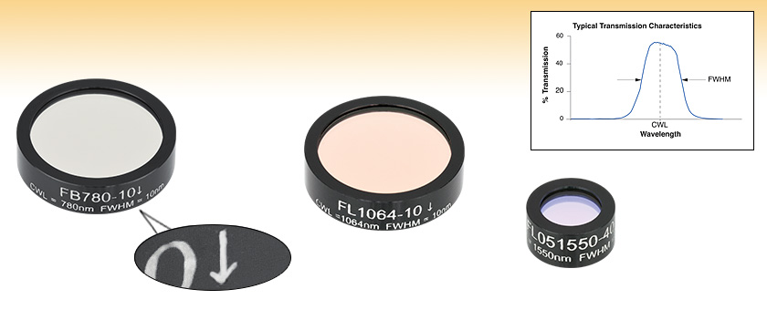
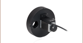
FB780-10
(Ø1")
Transmission Direction Indicator
FL1064-10
(Ø1")
FL051550-40
(Ø1/2")


Please Wait

Please see the Tutorial tab for more information about the structure of the filter and the transmission direction arrow.


Features
- Central Wavelengths from 700 nm to 1650 nm
- 3, 10, 12, 25, 30, or 40 nm Bandpass Regions
- Ø1/2" or Ø1" Mounted Filters
- Edge-Scribed for Superb Long-Term Stability
- Typical Transmission Plots Available for Every Filter
- Laser Line Filters for Popular Diode and Nd:YAG Laser Lines
The bandpass and laser line filters shown on this page feature center wavelengths of 700 nm to 1650 nm. Transmission and optical density curves for individual filters are available by clicking on the blue info icon (![]() ) for each individual filter below. Each filter is mounted in a black anodized aluminum ring with an outer diameter of Ø1/2" or Ø1" and a maximum edge thickness of 6.3 mm. Please note that Ø1/2" filter options are highlighted in green in the tables below.
) for each individual filter below. Each filter is mounted in a black anodized aluminum ring with an outer diameter of Ø1/2" or Ø1" and a maximum edge thickness of 6.3 mm. Please note that Ø1/2" filter options are highlighted in green in the tables below.
Thorlabs' bandpass filters provide one of the simplest ways to transmit a well-defined wavelength band of light, while rejecting other unwanted radiation. Their design is essentially that of a thin film Fabry-Perot Interferometer formed by vacuum deposition techniques and consists of two reflecting stacks, separated by an even-order spacer layer. These reflecting stacks are constructed from alternating layers of high and low refractive index materials, which can have a reflectance in excess of 99.99%. By varying the thickness of the spacer layer and/or the number of reflecting layers, the central wavelength and bandwidth of the filter can be altered. Because of the Fabry-Perot design, these filters are designed for use at a 0° angle of incidence (AOI). The transmission band will be shifted in wavelength and may be reduced when used with other AOIs. For more details on the properties and construction of our bandpass filters, please see the Tutorial tab.
These types of filters display very high transmission in the bandpass region, but the spectral range of blocked light on either side of the bandpass region is narrow. To compensate for this, an additional blocking component is added, which is either an all dielectric or a metal-dielectric depending on the requirements of the filter. Although this additional blocking component will eliminate any unwanted out-of-band radiation, it also reduces the filters' overall transmission throughput. For applications with demanding wavefront requirements, such as imaging, please consider our premium bandpass filters.
Each filter is housed in a black anodized aluminum ring that is labeled with an arrow indicating the design propagation direction. The ring makes handling easier and enhances the blocking OD by limiting scattering. These filters can be mounted in our extensive line of filter mounts and wheels. As the mounts are not threaded, retaining rings will be required to mount the filters in one of our internally-threaded lens tubes. We do not recommend removing the filter from its mount, as the filter consists of several layers of glass that are held together with epoxy and the mounting ring. These glass layers are necessary to protect the dielectric coating from the atmosphere; exposure would significantly reduce the filter's transmission efficiency over time.
Please note that due to the gradual breakdown of the dielectric coatings (primarily due to water vapor), our bandpass filters have a typical lifetime of two years. Older filters will experience a decrease of overall transmission in the passband.
| Additional Bandpass Filters | |||||
|---|---|---|---|---|---|
| UV/Visible Bandpass Filters 340 - 694.3 nm CWLs |
NIR Bandpass Filters 700 - 1650 nm CWLs |
MIR Bandpass Filters 1750 - 9500 nm CWLs |
Premium Bandpass Filters 355 - 1550 nm CWLs |
Bandpass Filter Kits | |
| We also offer custom bandpass filters with other central wavelengths or FWHM. To request a quote, contact Tech Support. | |||||
| Common Specifications | |
|---|---|
| Out of Band Transmission | <0.01% |
| Housing Diameter | 1/2" (Laser Line) 1" (Bandpass) |
| Housing Diameter Tolerance | +0.0 / -0.2 mm |
| Clear Aperture | Ø8.6 mm (Min) for Ø1/2" Ø21 mm (Min) for Ø1" |
| Thickness | <6.3 mm |
| Surface/Coating Quality | 80-50 Scratch-Dig |
| Edge Treatment | Mounted in Black Anodized Aluminum Ring |
| Edge Markings | CWL-FWHM ↑ Lot Number; The Arrow Points in the Direction of the light transmission |
| Substrates | Schott Borofloat and Soda Lime |
| Optimum Operating Temperature | 23 °C |
| Operating Temperature | -50 to 80 °C |

Click to Enlarge
The number of layers shown in this schematic is not indicative of the number of layers in an actual bandpass filter. Also the drawing is not to scale.
Bandpass Filter Structure
A bandpass filter is created by depositing layers of material on the surface of the substrate. Typically, there are several dielectric stacks separated by spacer layers. The dielectric stack is composed of a large number of alternating layers of low-index and high-index dielectric material. The thickness of each layer in the dielectric stack is λ/4, where λ is the central wavelength of the bandpass filter (i.e. the wavelength with the highest transmittance through the filter). The spacer layers are placed in between the dielectric stacks and have a thickness of (nλ)/2, where n is an integer. The spacer layers can be formed from colored glass, epoxy, dyes, metallic, or dielectric layers. A Fabry-Perot cavity is formed by each spacer layer sandwiched between dielectric stacks. The filter is mounted in an engraved metal ring for protection and ease of handling.
Filter Operation Overview
The constructive interference conditions of a Fabry-Perot cavity allow light at the central wavelength, and a small band of wavelengths to either side, to be transmitted efficiently, while destructive interference prevents the light outside the passband from being transmitted. However, the band of blocked wavelengths on either side of the central wavelength is small. In order increase the blocking range of the filter, materials with broad blocking ranges are used for or coated onto the spacer layers and the substrate. Although these materials effectively block out of band transmission of incident radiation they also decrease the transmission through the filter in the passband.

FB800-10 and FB800-40 filters were used to make the measurement that resulted in the plot above.
Filter Orientation
An engraved arrow on the edge of the filter is used to indicate the recommended direction for the transmission of light through the filter. Although the filter will function with either side facing the source, it is better to place the coated side toward the source. This will minimize any thermal effects or possible thermal damage that blocking intense out-of-band radiation might cause due to the absorption of the out-of-band radiation by the substrate or colored glass filter layers. The plot to the right was made by illuminating the filter with a low intensity broadband light and measuring the transmission as a function of wavelength. The plot shows that the transmission direction through the filter has very little effect on the intensity and the spectrum of the light transmitted through the filter. The minimal variation between the forward and backward traces is most likely due to a small shift in the incident angle of the light on the filter introduced when the filter was removed, flipped over, and replaced in the jig.
The filter is intended to be used with collimated light normally incident on the surface of the filter. For uncollimated light or light striking the surface and an angle not normally incident to the surface the central wavelength (wavelength corresponding to peak transmission) will shift toward lower wavelengths and the shape of the transmission region (passband) will change. Varying the angle of incidence by a small amount can be used to effectively tune the passband over a narrow range. Large changes in the incident angle will cause larger shifts in the central wavelength but will also significantly distort the shape of the passband and, more importantly, cause a significant decrease in the transmittance of the passband.
Filter Temperature
The central wavelength of the bandpass filter can be tuned slightly (~1 nm over the operating range of the filter) by changing the temperature of the filter. This is primarily due to the slight thermal expansion or contraction of the layers.
| Posted Comments: | |
Marco Sousa
(posted 2020-08-21 12:16:03.683) Hi, I would like to know the spectrum and Transmission in function of its incident angle. YLohia
(posted 2020-09-17 09:06:10.0) Hello, thank you for contacting Thorlabs. I have reached out to you directly with this information for the FB1000-10. Aleksandr Pikalev
(posted 2020-02-10 17:05:50.257) Hello.
We use a FB810-10 filter to capture an image of an argon discharge for 810 and 811 nm spectral lines. We put the filter on a camera lenses. Unfortunately, we see rings in the images, which seems to be caused by an interference on the filter. We tried another lenses, but the rings were present anyway. The rings are not visible without the filter, and they moves when I move the filter. The rings become more contrast if I make the lenses diaphragm smaller, but their size does not change.
Could you advise how to use the filter to prevent this problem? Would it be better if I use a hard-coated filter FBH810-10?
Yous sincerely,
Aleksandr Pikalev nbayconich
(posted 2020-02-19 08:22:37.0) Thank you for contacting Thorlabs, our standard bandpass filters such as FB810-10 consist of several layers of substrate and absorptive glass which can increase the amount of surface reflections. Our premium hardcoated filters such as the FBH810-10 consist of a single piece of UV fused silica coated with interference coating, these filters should reduce the amount of reflection seen which can contribute to the inteference patterns you've seen in your setup. I will reach out to you directly to discuss your application. Van Rudd
(posted 2020-01-09 11:38:06.693) What is the WFE obtained when passing through these filters?
I am trying to filter a 1610 nm laser, so I cannot use your premium bandpass filters. YLohia
(posted 2020-01-14 04:36:22.0) Thank you for contacting Thorlabs. We have not yet performed tests for the Wavefront Error on these optics. The construction of these filters has several substrates that are laminated together, creating a fully blocked filter. We estimate the WFE to be in the 2-3 waves range. Vijay Singh
(posted 2019-05-07 17:39:29.313) Hi, I would like to check the damage threshold power? I would like to buy FB1300-30 and my input laser beam power is few watts, does it work with that incident power? YLohia
(posted 2019-05-16 08:50:48.0) Hello, thank you for contacting Thorlabs. Based on our direct discussion, you are using an 8 Watt (CW) beam in the 400nm-1800nm beam. While we do not have a formal damage threshold for this filter, we do not expect this filter to be able to handle this power level since most of the energy at the shorter (visible) wavelengths will be absorbed. You may have better luck if you use an absorptive ND filter to attenuate your beam prior to using this bandpass filter or using the FLH1030-10, which would have a higher damage threshold (no formal testing for CW in this wavelength range either, but this one is expected to perform better). petros.vlavakis
(posted 2018-11-26 17:47:34.147) dear Sir or Madam,
My name is petros vlavakis and i am workin on the feald of soot formation.
I am interasted to by a filter in order to see the soot (carbon black) radiation at temperatures around 1500 K.
So i need a bandpass filter that lets the ration in wave lengths throuth. Do you have maybe any idea what kind of filter i could use for this and at wich WL?
thank you very much
Yous sincerely
Peros Vlavakis YLohia
(posted 2018-11-30 08:39:17.0) Hello Petros, thank you for contacting Thorlabs. Based on our direct discussion, it looks like you're trying to transmit 650nm and attenuate all light < 650nm. For this, we recommend our long pass filters such as the FEL0650 and FELH0650. You may want to angle-tune the filter slightly to shift the cut-on wavelength a little lower. As a rule of thumb, when the angle of incidence goes from 0° to 45°, the center wavelength shifts down by about 10%. luis.z
(posted 2018-09-27 15:44:02.317) I am interested in buying the bandpass filter FB1300-30, I am wondering if you can sell the filter without the aluminum ring. If so, can I get a quotation for it.
Regards, YLohia
(posted 2018-10-01 08:39:24.0) Hello, thank you for contacting Thorlabs. We will reach out to you directly to discuss the possibility of offering this custom item. Please note that we do not recommend removing the filter from its mount, as the filter consists of several layers of glass that are held together with epoxy and the mounting ring. These glass layers are necessary to protect the dielectric coating from the atmosphere; exposure would significantly reduce the filter's transmission efficiency over time. egalvez
(posted 2017-11-03 09:51:50.05) Dear Thorlabs:
There is a type of optical experiments that many physicists do: producing photon pairs via spontaneous parametric down-conversion. These experiments are used for research into quantum information, but they are also used in undergraduate labs. They use the popular 405-nm GaN diode laser. The down-conversion process produces pairs of photons at twice the wavelength: 810 nm. So people use bandpass filters centered at 810 nm. Your selection of bandpass filters is limited: there is only one filter at 810 nm, with 10-nm bandwidth. It would be useful to have other bandwidths, 40-nm especially, but also 2 nm and 1 nm.
Thank you, Enrique Galvez tfrisch
(posted 2018-01-03 03:42:38.0) Hello, thank you for contacting Thorlabs. As I understand SPDC, the detection of the 810nm signal requires a significant extinction of the blue excitation. You may wan to look at FELH0600 for this application. I will reach out to you directly to discuss this. ka
(posted 2017-09-11 12:35:31.913) Greetings, i was wondering whats the refractive index for the product FB870-10, as it will help me with a simulation,
Best Regards tfrisch
(posted 2017-09-20 04:54:56.0) Hello, thank you for contacting Thorlabs. These filters have substrate layers, dielectric layers, and absorptive layers, and the exact design would be proprietary. While we cannot give you the thicknesses and indices of every layer, please reach out to us at TechSupport@Thorlabs.com to discuss your application as we may be able to provide the information you need in another form. andy27229937
(posted 2017-06-14 07:24:46.153) Hi Sir,
How can I know the maximum optical damage power(watt) of the line filter FB1550-12?
Thank you.
Andy tfrisch
(posted 2017-06-30 03:00:53.0) Hello, thank you for contacting Thorlabs. It looks like you have already been in contact with our Technical Support team about the specifics of your application. While we don't have a formal damage threshold that would cover both blocking and transmitting regions, we are glad to discuss your individual source to make a recommendation at TechSupport@Thorlabs.com schaefer
(posted 2017-02-03 11:02:29.893) Hi! I have two questions:
- I would like to know how much of a shift of the central wavelength Ic an expect when using these filters at 45° (some sort of plot showing the distortion would be nice as well)
- Is the backside fully reflective and if so, what is the expected reflectivity as a function of wavelength (e.g. is it silver coated?).
thank you for your help! tfrisch
(posted 2017-02-13 02:45:10.0) Hello, thank you for contacting Thorlabs. The rule of thumb is that about 10 degrees will shift the center wavelength about 5-6nm, but that will be dependent on several factors including the starting CWL. Unfortunately, we do not keep data on the distortion of the passband, but it does tend to become significant at about 20 degrees. Lastly, the back is not silver coated. While the composition of the filter is proprietary, it will be a mix of dielectric layers and absorbing layers. achim.modlich
(posted 2016-08-04 16:32:16.85) Hello,
please provide a Quote for
2 pcs FB880-10 ø1"
2 pcs FB960-10 ø1"
What is typically the temperature dependency / coeff -> shift in nm/K ?
I Need an exact value / graph nm(T)as I want to use These filters as reference wavelenghts to check spectrometers within automated measurements.
Thanks and best regards
Achim Modlich daniel.brunner
(posted 2016-02-08 11:35:17.377) I would like to use the FL830-10 to select a 830 nm source from a continuum, placing the filter at 45 degree inside the beam path. The light above the 830 source is supposed to be used for spectroscopy, so is the band from 850 nm - 1000 nm absorbed by the filter or is it reflected? besembeson
(posted 2016-02-10 01:29:16.0) Response from Bweh at Thorlabs USA: These are absorbed. Note that these are designed for 0deg AOI. At 45deg AOI, the center wavelength will not be 830nm, but will be well shifted to a much lower wavelength. I will contact you with an example on the shift you should expect. jcdr
(posted 2015-08-31 19:01:55.393) We just received the filter and the camera today, only to discover that the filter diameter is too large to fit inside the CS mount cylinder of the camera. But we also found that the camera have a nice filter holder inside. The supported filter format is 14mm square. Is there any possibility to get the FB850-10 in a raw 14mm X 14mm X 1mm format ? besembeson
(posted 2015-09-29 11:47:56.0) Response from Bweh at Thorlabs USA: I will follow-up regarding providing this as a special item. lzhou
(posted 2014-08-22 10:08:44.91) We are interested in measuring the signal of singlet oxygen, which peaks at 1270-1280nm. I was wondering about the price of such filters. Thank you. jlow
(posted 2014-09-18 02:29:24.0) Response from Jeremy at Thorlabs: The FB1300-30 might work for you. The latest price is listed on our webpage. We will contact you directly about this. zyang01
(posted 2014-04-21 13:46:30.127) Hi, we have a number of your bandpass and edgepass filters (FB1050-10, FEL950-1,... pictures are available upon request)that are falling apart after a few uses, often times breaking in the process. It seems this issue has been going on for some time. I just want to ask if you are in the process of fixing the issue or not before we buy any more of your filters. Thanks. Zhou Yang jlow
(posted 2014-04-23 01:42:14.0) Response from Jeremy at Thorlabs: If you are using a mount that holds an optic with a setscrew, you can debond the filter from the housing by over-tightening the setscrew. I will contact you directly to check into the cause your filters have debonded. emmanuel.maillart
(posted 2013-07-16 10:40:11.0) Hello.
FB810-10 is indicated as having a central wavelength of 810+/-2nm and a FWHM of 10+/-2nm.
But, when I download the Excel file containing a typical spectrum of transmission for this reference, the typical spectrum has a central wavelength of 807nm and a FWHM of 16nm.
Why is this typical spectrum not conform to the specifications? sharrell
(posted 2013-07-17 15:15:00.0) Response from Sean at Thorlabs: Thank you for your feedback. We’ve updated our plot for the FB810-10 to represent the current performance of the item. We are also in the process of checking all of our bandpass filter graphs to ensure that they agree with our current specifications. tcohen
(posted 2013-01-02 09:34:00.0) Response from Tim at Thorlabs to Vincent: The central wavelength of an interference filter can shift with increasing or decreasing temperatures. This effect, which is due primarily to the expansion or contraction of the spacer layers and the concomitant change in their refractive indices, is extremely small over normal operating ranges (˜ 0.01 nm/°C). Prolonged operation at high temperatures (>75° C) will irreversibly set the central wavelength lower. Temperatures above 125° C should be avoided.
Though interference filters will function at -50° C or lower, the cooling rate should not be allowed to exceed 5° C per minute. An excessive cooling rate can cause the glass substrate to crack or the filter to delaminate due to differential thermal contraction. vincent.mariage
(posted 2012-12-17 04:53:43.747) Hello,
I would like to know the shift in nm with the temperature of the central wavelength of the filter FL905-10. Thank you in advance. Vincent Mariage jlow
(posted 2012-09-28 16:25:00.0) Response from Jeremy at Thorlabs: Water moisture is typically the cause for the degradation of these dielectric filters. The coatings are somewhat porous and the presence of water will alter how the layers interact with each other. The absorptive glass used in the construction of these filters can also be affected by water moisture as well. Both the transmission characteristic and the surface polish quality can be affected by water moisture. itarres1
(posted 2012-09-27 20:34:19.0) I would like to know what causes the gradual breakdown of the dielectric coatings in the bandpass filters.
How is the filter performance affected?
What is the expected decrease in performance for a filter working outdoors v/s indoors?
I'll be using a FB850-10 or FB850-40 filter.
Thank you in advance.
Ignacio Tarres. tcohen
(posted 2012-07-12 12:16:00.0) Response from Tim at Thorlabs: Thank you for your interest in our custom capabilities! In order to answer this, we would need more information such as the dimensions, surface quality, transmission requirements, quantity and tolerances on both the FWHM and CWL. We have a dedicated team of members who quote custom optics and we will contact you to discuss your needs so that we can provide information for this custom quote. avle
(posted 2012-07-12 05:35:41.0) what is the typical cost for a custom filter? with properties of 1280nm bandpass, 10nm FWHM, tolerence +-5nm?
Thanks! tcohen
(posted 2012-04-03 09:52:00.0) Response from Tim at Thorlabs: These filters are specified at 0 degrees AOI. As the angle increases, the transmission curve will migrate towards lower wavelengths. However, please note that the shape of the transmission curve will also deform as the AOI increases beyond small angles. To be able to provide more information, I have contacted you to find out your input angle. s.prikasky
(posted 2012-04-02 15:11:00.0) Dear Company,
we are using your filter FL-905-10, behind this filter is camera. This simply optical system we want use for laser tracking system. I can not find on your web graph with diagram how depending output laser beam power (attenuation in filter) on input angle. hidalgo
(posted 2012-03-22 11:15:34.0) Hi, I need a bandpass filter for 800nm CWL with FWHM around 3nm or less, I'm working with 130fs pulses of 2.2mJ at 1kHZ, I'll use the filter to shorten the pulse to ps. Is it possible that you can provide a filter with this characteristics? tcohen
(posted 2012-03-09 19:11:00.0) Response from Tim at Thorlabs: Thank you for your feedback. Because of the many variables involved we don’t have specific damage thresholds for all of our filters. That tab was on the page in error and has been removed. The important thing to remember with these filters will be that the damage threshold inside the bandpass region will be higher than the outside regions, as these will be more absorptive. As a guideline for these filters we recommend not exceeding 1W/cm^2 CW and .3J/cm^2 with 10ns pulse. Please use this as a reference, but remember this will be restrictive to the bandpass region and will also be variable between filters. user
(posted 2012-03-09 15:35:09.0) How can we learn damage threshold of filters by [the damage threshold tub]??? There seems only data on BB1-E02 mirror. kimiwang1111
(posted 2011-11-15 16:46:05.0) If I want to use the filter "FB750-40" for my optical system, and I will simulate it by ray tracing software. How to set the refractive index of the filter FB750-40? jjurado
(posted 2011-06-30 09:40:00.0) Response from Javier at Thorlabs to jochen.reichel: Thank you very much for contacting us. The spec sheet with transmission information for this filter is currently not on the web. We will upload this file shortly, and in the meantime, I will send this information directly to your e-mail. jochen.reichel
(posted 2011-06-30 04:03:03.0) Where can I find the spec sheet / transmission plot for the laser line filter FL830-10? jjurado
(posted 2011-05-18 10:30:00.0) Response from Javier at Thorlabs to t.dzelzainis: Thank you very much for your feedback. We are currently working on a project to include transmission data for all our interference and neutral density filters. In the meantime, we can send you raw transmission data for any filter you may be interested in. I will contact you directly to get your requirements. t.dzelzainis
(posted 2011-05-18 14:21:35.0) could you please please please show youre transmission plots with a log scale on the y-axis. or even better, make the data available. A plot with a linear y-axis showing a transmission of ~0 outside of some range is not particularly useful when you are interested in exact ratios and extinction ratios are important (i.e. when dealing with low signal in the transmission band, but high signal elsewhere). This request can also be applied to some of your nd filter plots. e.g trying to estimate the transmission of nd40a for 350nm tor
(posted 2010-11-16 08:07:09.0) A response from Tor at Thorlabs to Dustin: Thank you for your interest in our laser line filters. As shown on the Specs tab, the FL1064-10 provides an OD >= 4 from the UV to 1150 nm. dustinkleckner
(posted 2010-11-15 18:44:18.0) In general, how well do the laser line filters block out of the main transmission band? Im specifically interested in the 1064-10 filter transmission in the 633-650 range. Thorlabs
(posted 2010-11-01 15:27:15.0) Response from Javier at Thorlabs to Scotttygett: I will contact you directly to get more details about the required filter. Scotttygett
(posted 2010-11-01 12:29:02.0) I have ordered two of these filters from Thorlabs and two from another supplier, specializing in NOS filters.
The main difference I noticed was that the shiny side of the other suppliers filter was not on the outside, but faced a tinted glass (the filter was unmounted). This made it much easier to not mar, and much easier to use for optical purposes where internal reflections might be an issue. Was this something that I could have requested? I imagine for laser mirroring one would want the front surface out. klee
(posted 2009-08-12 15:53:12.0) A response from Ken at Thorlabs to thomas.woggon: We will send you the transmission spectrum by email. thomas.woggon
(posted 2009-08-12 15:28:52.0) Is it possible to get a measured transmission spectrum or the calculated transmission curve for the FL632.8-1 laser line filter? We want to use it for QM purposes on high resolution spectrometers.
Regards Laurie
(posted 2009-05-07 15:14:16.0) A response from Laurie at Thorlabs to jean.fortin: Someone from our technical support staff will be getting in contact with you shortly, as we need some additional information to provide a quote. jean.fortin
(posted 2009-05-06 21:24:37.0) I am looking for large laser line filters (532 and 1064) either square or circular. 3 inch and more would be ok. Thank you Tyler
(posted 2008-11-20 15:14:24.0) A response from Tyler at Thorlabs to apalmentieri: Given the current layout of the page it is not possible to further separate out the products by the bandwidth. However, we could consider creating a page of narrow bandwidth filters or put the products in a sortable table (see http://www.thorlabs.com/NewGroupPage11.cfm?ObjectGroup_ID=7 for an example). If either of these options would make finding the product you are looking for easier, please let me know. By the way, the current layout of the page was chosen so that it would be easy to locate a filter with the correct wavelength and at that point be able to see what bandwidth options were available as standard products. Thank you for taking the time to submit your feedback, can you please let me know if either of the options I proposed will help? apalmentieri
(posted 2008-11-19 16:15:54.0) To make some of our laser line filters more prevalent, it may make sense to seperate the narrow band(1nm for lower wavelengths and 3nm for higher wavelengths, 1064nm) and standard bands. Requests for these filters have come in before and providing them with their own section or webpage may make them easier to find. Tyler
(posted 2008-06-03 12:11:36.0) A response from Tyler at Thorlabs to acable: A tutorial tab was added to the page with some information about the properties of these filters. If anyone reading this tutorial would like to suggest or provide additional content please post the information in the feedback tab or email technicalmarketing@thorlabs.com. acable
(posted 2007-11-15 17:48:01.0) On the Overview tab it would be nice to provide details on the directional nature of the filter, along with an explanation of why the fitler is directional. Could you also provide a representative plots of the performance of the filters, showing how the performance is compromised when he direction of light is in the wrong direction would also be great.
When using the filters i noticed that the arrow indicating the recommended direction is not as clearly marked as one would hope, could you consider taking a closeup photograph of the indicator, and display it in the main presentation area of this page, along with a simple statement indicating the meaning of the indicator. |
| Item # | CWLa | FWHMb | T (Min)c | Blockingd | Transmission/ OD Datae |
Laser Line | Size |
|---|---|---|---|---|---|---|---|
| FB700-10 | 700 ± 2 nm | 10 ± 2 nm | 50% | 200 - 1200 nm | N/A | Ø1" | |
| FB700-40 | 700 ± 8 nm | 40 ± 8 nm | 70% | 200 - 1150 nm | N/A | Ø1" | |
| FB710-10 | 710 ± 2 nm | 10 ± 2 nm | 50% | 200 - 1200 nm | N/A | Ø1" | |
| FB720-10 | 720 ± 2 nm | 10 ± 2 nm | 50% | 200 - 1200 nm | N/A | Ø1" | |
| FB730-10 | 730 ± 2 nm | 10 ± 2 nm | 50% | 200 - 1200 nm | N/A | Ø1" | |
| FL730-10 | 730 ± 2 nm | 10 ± 2 nm | 70% | 200 - 1150 nm | Diode | Ø1" | |
| FB740-10 | 740 ± 2 nm | 10 ± 2 nm | 50% | 200 - 1200 nm | N/A | Ø1" | |
| FB750-10 | 750 ± 2 nm | 10 ± 2 nm | 50% | 200 - 1200 nm | N/A | Ø1" | |
| FB750-40 | 750 ± 8 nm | 40 ± 8 nm | 70% | 200 - 1150 nm | N/A | Ø1" | |
| FB760-10 | 760 ± 2 nm | 10 ± 2 nm | 50% | 200 - 1200 nm | N/A | Ø1" | |
| FB770-10 | 770 ± 2 nm | 10 ± 2 nm | 50% | 200 - 1200 nm | N/A | Ø1" | |
| FB780-10 | 780 ± 2 nm | 10 ± 2 nm | 50% | 200 - 1200 nm | N/A | Ø1" | |
| FL05780-10 | 780 ± 2 nm | 10 ± 2 nm | 70% | 200 - 1100 nm | Diode | Ø1/2" | |
| FL780-10 | 780 ± 2 nm | 10 ± 2 nm | 70% | 200 - 1150 nm | Diode | Ø1" | |
| FB790-10 | 790 ± 2 nm | 10 ± 2 nm | 50% | 200 - 1200 nm | N/A | Ø1" |
- Center Wavelength
- Full Width Half Max
- Minimum Transmission at Center Wavelength
- <0.01% (<-40 dB)
- Click on
 for a plot and downloadable data. Measured data accounts for all losses including Fresnel reflections. Please note that transmission is only guaranteed for the specified center wavelength and that the data in the plots is typical. Performance may vary from lot to lot.
| Item # | CWLa | FWHMb | T (Min)c | Blockingd | Transmission/ OD Datae |
Laser Line | Size |
|---|---|---|---|---|---|---|---|
| FB800-10 | 800 ± 2 nm | 10 ± 2 nm | 50% | 200 - 1200 nm | N/A | Ø1" | |
| FB800-40 | 800 ± 8 nm | 40 ± 8 nm | 70% | 200 - 1150 nm | N/A | Ø1" | |
| FB810-10 | 810 ± 2 nm | 10 ± 2 nm | 50% | 200 - 1200 nm | N/A | Ø1" | |
| FB820-10 | 820 ± 2 nm | 10 ± 2 nm | 50% | 200 - 1200 nm | N/A | Ø1" | |
| FB830-10 | 830 ± 2 nm | 10 ± 2 nm | 50% | 200 - 1200 nm | N/A | Ø1" | |
| FL830-10 | 830 ± 2 nm | 10 ± 2 nm | 70% | 200 - 1150 nm | Diode | Ø1" | |
| FB840-10 | 840 ± 2 nm | 10 ± 2 nm | 50% | 200 - 1200 nm | N/A | Ø1" | |
| FB850-10 | 850 ± 2 nm | 10 ± 2 nm | 50% | 200 - 1200 nm | N/A | Ø1" | |
| FL05850-10 | 850 ± 2 nm | 10 ± 2 nm | 70% | 200 - 1100 nm | Diode | Ø1/2" | |
| FL850-10 | 850 ± 2 nm | 10 ± 2 nm | 70% | 200 - 1150 nm | Diode | Ø1" | |
| FB850-40 | 850 ± 8 nm | 40 ± 8 nm | 70% | 200 - 1150 nm | N/A | Ø1" | |
| FB860-10 | 860 ± 2 nm | 10 ± 2 nm | 50% | 200 - 1200 nm | N/A | Ø1" | |
| FB870-10 | 870 ± 2 nm | 10 ± 2 nm | 50% | 200 - 1200 nm | N/A | Ø1" | |
| FB880-10 | 880 ± 2 nm | 10 ± 2 nm | 50% | 200 - 1200 nm | N/A | Ø1" | |
| FL880-10 | 880 ± 2 nm | 10 ± 2 nm | 50% | 200 - 1150 nm | Diode | Ø1" | |
| FB880-40 | 880 ± 8 nm | 40 ± 8 nm | 70% | 200 - 1150 nm | N/A | Ø1" | |
| FB880-70 | 880 ± 8 nm | 70 ± 8 nm | 70% | 200 - 1150 nm | N/A | Ø1" | |
| FB890-10 | 890 ± 2 nm | 10 ± 2 nm | 50% | 200 - 1200 nm | N/A | Ø1" |
- Center Wavelength
- Full Width Half Max
- Minimum Transmission at Center Wavelength
- <0.01% (<-40 dB)
- Click on for a plot and downloadable data. Measured data accounts for all losses including Fresnel reflections. Please note that transmission is only guaranteed for the specified center wavelength and that the data in the plots is typical. Performance may vary from lot to lot.
| Item # | CWLa | FWHMb | T (Min)c | Blockingd | Transmission/ OD Datae |
Laser Line | Size |
|---|---|---|---|---|---|---|---|
| FB900-10 | 900 ± 2 nm | 10 ± 2 nm | 50% | 200 - 1200 nm | N/A | Ø1" | |
| FB900-40 | 900 ± 8 nm | 40 ± 8 nm | 70% | 200 - 1150 nm | N/A | Ø1" | |
| FL905-10 | 905 ± 2 nm | 10 ± 2 nm | 70% | 200 - 1150 nm | Diode | Ø1" | |
| FL905-25 | 905 ± 5 nm | 25 ± 5 nm | 70% | 200 - 1150 nm | Diode | Ø1" | |
| FB910-10 | 910 ± 2 nm | 10 ± 2 nm | 50% | 200 - 1200 nm | N/A | Ø1" | |
| FB920-10 | 920 ± 2 nm | 10 ± 2 nm | 50% | 200 - 1200 nm | N/A | Ø1" | |
| FB930-10 | 930 ± 2 nm | 10 ± 2 nm | 50% | 200 - 1200 nm | N/A | Ø1" | |
| FB940-10 | 940 ± 2 nm | 10 ± 2 nm | 50% | 200 - 1200 nm | N/A | Ø1" | |
| FB950-10 | 950 ± 2 nm | 10 ± 2 nm | 50% | 200 - 1200 nm | N/A | Ø1" | |
| FB960-10 | 960 ± 2 nm | 10 ± 2 nm | 50% | 200 - 1200 nm | N/A | Ø1" | |
| FB970-10 | 970 ± 2 nm | 10 ± 2 nm | 50% | 200 - 1200 nm | N/A | Ø1" | |
| FB980-10 | 980 ± 2 nm | 10 ± 2 nm | 50% | 200 - 1200 nm | N/A | Ø1" | |
| FB990-10 | 990 ± 2 nm | 10 ± 2 nm | 50% | 200 - 1200 nm | N/A | Ø1" |
- Center Wavelength
- Full Width Half Max
- Minimum Transmission at Center Wavelength
- <0.01% (<-40 dB)
- Click on for a plot and downloadable data. Measured data accounts for all losses including Fresnel reflections. Please note that transmission is only guaranteed for the specified center wavelength and that the data in the plots is typical. Performance may vary from lot to lot.
| Item # | CWLa | FWHMb | T (Min)c | Blockingd | Transmission/ OD Datae |
Laser Line | Size |
|---|---|---|---|---|---|---|---|
| FB1000-10 | 1000 ± 2 nm | 10 ± 2 nm | 45% | 200 - 3000 nm | N/A | Ø1" | |
| FB1050-10 | 1050 ± 2 nm | 10 ± 2 nm | 45% | 200 - 3000 nm | N/A | Ø1" | |
| FL051064-3 | 1064 ± 0.6 nm | 3 ± 0.6 nm | 55% | 200 - 1100 nm | Nd:YAG | Ø1/2" | |
| FL1064-3 | 1064 ± 0.6 nm | 3 ± 0.6 nm | 45% | 200 - 1150 nm | Nd:YAG | Ø1" | |
| FL051064-10 | 1064 ± 2 nm | 10 ± 2 nm | 70% | 200 - 1100 nm | Nd:YAG | Ø1/2" | |
| FL1064-10 | 1064 ± 2 nm | 10 ± 2 nm | 70% | 200 - 1150 nm | Nd:YAG | Ø1" | |
| FB1070-10 | 1070 ± 2 nm | 10 ± 2 nm | 70% | 200 - 1200 nm | N/A | Ø1" | |
| FB1100-10 | 1100 ± 2 nm | 10 ± 2 nm | 40% | 200 - 3000 nm | N/A | Ø1" | |
| FB1150-10 | 1150 ± 2 nm | 10 ± 2 nm | 40% | 200 - 3000 nm | N/A | Ø1" | |
| FL1152-10 | 1152 ± 2 nm | 10 ± 2 nm | 45% | 200 - 3000 nm | HeNe | Ø1" | |
| FB1200-10 | 1200 ± 2 nm | 10 ± 2 nm | 40% | 200 - 3000 nm | N/A | Ø1" | |
| FB1250-10 | 1250 ± 2 nm | 10 ± 2 nm | 40% | 200 - 3000 nm | N/A | Ø1" |
- Center Wavelength
- Full Width Half Max
- Minimum Transmission at Center Wavelength
- <0.01% (<-40 dB)
- Click on for a plot and downloadable data. Measured data accounts for all losses including Fresnel reflections. Please note that transmission is only guaranteed for the specified center wavelength and that the data in the plots is typical. Performance may vary from lot to lot.
| Item # | CWLa | FWHMb | T (Min)c | Blockingd | Transmission/ OD Datae |
Laser Line | Size |
|---|---|---|---|---|---|---|---|
| FB1300-12 | 1300 ± 2.4 nm | 12 ± 2.4 nm | 40% | 200 - 3000 nm | N/A | Ø1" | |
| FB1300-30 | 1300 ± 6 nm | 30 ± 6 nm | 40% | 200 - 1850 nm | N/A | Ø1" | |
| FB1310-12 | 1310 ± 2 nm | 12 ± 2.4 nm | 40% | 200 - 3000 nm | N/A | Ø1" | |
| FB1320-12 | 1320 ± 2 nm | 12 ± 2.4 nm | 40% | 200 - 3000 nm | N/A | Ø1" | |
| FB1330-12 | 1330 ± 2 nm | 12 ± 2.4 nm | 40% | 200 - 3000 nm | N/A | Ø1" | |
| FB1340-12 | 1340 ± 2 nm | 12 ± 2.4 nm | 40% | 200 - 3000 nm | N/A | Ø1" | |
| FB1350-12 | 1350 ± 2.4 nm | 12 ± 2.4 nm | 35% | 200 - 3000 nm | N/A | Ø1" | |
| FB1400-12 | 1400 ± 2.4 nm | 12 ± 2.4 nm | 35% | 200 - 3000 nm | N/A | Ø1" | |
| FB1450-12 | 1450 ± 2.4 nm | 12 ± 2.4 nm | 35% | 200 - 3000 nm | N/A | Ø1" | |
| FB1480-12 | 1480 ± 2 nm | 12 ± 2.4 nm | 35% | 200 - 3000 nm | N/A | Ø1" | |
| FB1490-12 | 1490 ± 2 nm | 12 ± 2.4 nm | 35% | 200 - 3000 nm | N/A | Ø1" |
- Center Wavelength
- Full Width Half Max
- Minimum Transmission at Center Wavelength
- <0.01% (<-40 dB)
- Click on for a plot and downloadable data. Measured data accounts for all losses including Fresnel reflections. Please note that transmission is only guaranteed for the specified center wavelength and that the data in the plots is typical. Performance may vary from lot to lot.
| Item # | CWLa | FWHMb | T (Min)c | Blockingd | Transmission/ OD Datae |
Laser Line | Size |
|---|---|---|---|---|---|---|---|
| FB1500-12 | 1500 ± 2.4 nm | 12 ± 2.4 nm | 35% | 200 - 1850 nm | N/A | Ø1" | |
| FB1510-12 | 1510 ± 2 nm | 12 ± 2.4 nm | 35% | 200 - 3000 nm | N/A | Ø1" | |
| FB1520-12 | 1520 ± 2 nm | 12 ± 2.4 nm | 35% | 200 - 3000 nm | N/A | Ø1" | |
| FB1530-12 | 1530 ± 2 nm | 12 ± 2.4 nm | 35% | 200 - 3000 nm | N/A | Ø1" | |
| FB1540-12 | 1540 ± 2 nm | 12 ± 2.4 nm | 35% | 200 - 3000 nm | N/A | Ø1" | |
| FB1550-12 | 1550 ± 2.4 nm | 12 ± 2.4 nm | 50% | 200 - 1850 nm | Diode | Ø1" | |
| FB1550-30 | 1550 ± 6 nm | 30 ± 6 nm | 50% | 200 - 1850 nm | Diode | Ø1" | |
| FL051550-40 | 1550 ± 8 nm | 40 ± 8 nm | 45% | 200 - 1850 nm | Diode | Ø1/2" | |
| FB1550-40 | 1550 ± 8 nm | 40 ± 8 nm | 45% | 200 - 1850 nm | Diode | Ø1" |
- Center Wavelength
- Full Width Half Max
- Minimum Transmission at Center Wavelength
- <0.01% (<-40 dB)
- Click on for a plot and downloadable data. Measured data accounts for all losses including Fresnel reflections. Please note that transmission is only guaranteed for the specified center wavelength and that the data in the plots is typical. Performance may vary from lot to lot.
| Item # | CWLa | FWHMb | T (Min)c | Blockingd | Transmission/ OD Datae |
Laser Line | Size |
|---|---|---|---|---|---|---|---|
| FB1560-12 | 1560 ± 2 nm | 12 ± 2.4 nm | 50% | 200 - 1850 nm | N/A | Ø1" | |
| FB1570-12 | 1570 ± 2 nm | 12 ± 2.4 nm | 50% | 200 - 1850 nm | N/A | Ø1" | |
| FB1580-12 | 1580 ± 2 nm | 12 ± 2.4 nm | 50% | 200 - 1850 nm | N/A | Ø1" | |
| FB1590-12 | 1590 ± 2 nm | 12 ± 2.4 nm | 50% | 200 - 1850 nm | N/A | Ø1" | |
| FB1600-12 | 1600 ± 2.4 nm | 12 ± 2.4 nm | 50% | 200 - 1850 nm | N/A | Ø1" | |
| FB1610-12 | 1610 ± 2 nm | 12 ± 2.4 nm | 50% | 200 - 1850 nm | N/A | Ø1" | |
| FB1620-12 | 1620 ± 2 nm | 12 ± 2.4 nm | 50% | 200 - 1850 nm | N/A | Ø1" | |
| FB1650-12 | 1650 ± 2.4 nm | 12 ± 2.4 nm | 50% | 200 - 1850 nm | N/A | Ø1" |
- Center Wavelength
- Full Width Half Max
- Minimum Transmission at Center Wavelength
- <0.01% (<-40 dB)
- Click on for a plot and downloadable data. Measured data accounts for all losses including Fresnel reflections. Please note that transmission is only guaranteed for the specified center wavelength and that the data in the plots is typical. Performance may vary from lot to lot.
The Bandpass Filter Kits contain ten of our most popular Ø1" mounted filters. The filter housings are labeled with the center wavelength, the Full Width Half Maximum (FWHM) of the bandpass region, lot number, and an arrow denoting the transmission direction. The filters come in a foam-lined storage box to help keep the optics organized and protected from physical damage. The table below contains a list of filters (and specs) included in each of the kits.
| Item # | Filter Included | Center Wavelength |
FWHM | T(min)a | Transmission/ OD Datab |
Filter Included | Center Wavelength |
FWHM | T(min)a | Transmission/ OD Datab |
|---|---|---|---|---|---|---|---|---|---|---|
| FKB-VIS-10 | FB350-10 | 350 ± 2 nm | 10 ± 2 nm | 25% | FB400-10 | 400 ± 2 nm | 10 ± 2 nm | 37% | ||
| FB450-10 | 450 ± 2 nm | 10 ± 2 nm | 45% | FB500-10 | 500 ± 2 nm | 10 ± 2 nm | 50% | |||
| FB550-10 | 550 ± 2 nm | 10 ± 2 nm | 50% | FB600-10 | 600 ± 2 nm | 10 ± 2 nm | 50% | |||
| FB650-10 | 650 ± 2 nm | 10 ± 2 nm | 50% | FB700-10 | 700 ± 2 nm | 10 ± 2 nm | 50% | |||
| FB750-10 | 750 ± 2 nm | 10 ± 2 nm | 50% | FB800-10 | 800 ± 2 nm | 10 ± 2 nm | 50% | |||
| FKB-VIS-40 | FB400-40 | 400 ± 8 nm | 40 ± 8 nm | 45% | FB450-40 | 450 ± 8 nm | 40 ± 8 nm | 45% | ||
| FB500-40 | 500 ± 8 nm | 40 ± 8 nm | 70% | FB550-40 | 550 ± 8 nm | 40 ± 8 nm | 70% | |||
| FB600-40 | 600 ± 8 nm | 40 ± 8 nm | 70% | FB650-40 | 650 ± 8 nm | 40 ± 8 nm | 70% | |||
| FB700-40 | 700 ± 8 nm | 40 ± 8 nm | 70% | FB750-40 | 750 ± 8 nm | 40 ± 8 nm | 70% | |||
| FB800-40 | 800 ± 8 nm | 40 ± 8 nm | 70% | FB850-40 | 850 ± 8 nm | 40 ± 8 nm | 70% | |||
| FKB-IR-10 | FB850-10 | 850 ± 2 nm | 10 ± 2 nm | 50% | FB900-10 | 900 ± 2 nm | 10 ± 2 nm | 50% | ||
| FB1000-10 | 1000 ± 2 nm | 10 ± 2 nm | 45% | FB1100-10 | 1100 ± 2 nm | 10 ± 2 nm | 40% | |||
| FB1200-10 | 1200 ± 2 nm | 10 ± 2 nm | 40% | FB1300-12 | 1300 ± 2.4 nm | 12 ± 2.4 nm | 40% | |||
| FB1400-12 | 1400 ± 2.4 nm | 12 ± 2.4 nm | 35% | FB1500-12 | 1500 ± 2.4 nm | 12 ± 2.4 nm | 35% | |||
| FB1550-12 | 1550 ± 2.4 nm | 12 ± 2.4 nm | 50% | FB1600-12 | 1600 ± 2.4 nm | 12 ± 2.4 nm | 50% |
- Minimum Transmission at Center Wavelength
- Click on for a plot and downloadable data. Measured data accounts for all losses including Fresnel reflections. Please note that transmission is only guaranteed for the specified center wavelength and that the data in the plots is typical. Performance may vary from lot to lot.