Vacuum-Compatible Ø1/2" Post System

- Ø1/2" Post System Components for Vacuum Use
- All Components are Shipped Double Vacuum Bagged
- Constructed of 316, 304L, and A4 Stainless Steel and
6061-T6 and 2024-T3 Aluminum
Ø1/2" Posts
TR3V
TR2V
TR1V
BA1V
Ø1/2" Post Holder Base
Vacuum-Compatible Ø1/2"
Post System: TR3V, PH3V, SS8S050V, and BA2V
PH2V
Ø1/2" Post Holder

Please Wait
Additional Vacuum-Compatible Components
Many of our other Optomechanical Components can be special ordered for vacuum use. Contact techsupport@thorlabs.com for details.

Click to Enlarge
All vacuum-compatible components are packaged inside a double vacuum bag.
Features
- Vacuum-Compatible Versions of Popular Optomechanical Components
- Ø1/2" Post System Includes Posts, Post Holders, Post Holder Bases, Thumbscrews, and Cap Screws
- All Components Compatible with 10-6 Torr Environments Directly Out of the Packaging
- Compatible with Lower Pressures with Additional User Processing
- All Components are Shipped Double Vacuum Bagged for Cleanroom Use
This page features vacuum-compatible versions of our most popular optomechanical components. These components are fabricated from specially-selected grades of stainless steel and aluminum for vacuum and cleanroom use. As shown in the photo to the right, all components are packaged in double airtight bags for cleanroom and vacuum chamber applications. We offer cap screws, setscrews, and washers for use with these items.
Vacuum Compatibility Information
Our vacuum-compatible optomechanics are chemically cleaned and prepared for vacuum applications before packaging. They are compatible directly out of the packaging with vacuum environments down to 10-6 Torr. With additional cleaning and processing, they can be used at even lower pressures, only limited by the outgassing rate of the aluminum or stainless steel (see the Vacuum Specs tab or the Specs tables below). The material properties of the aluminum or stainless steel and the cleaning methods completed by the end user should be used to determine the appropriateness of these products and materials in a specific vacuum system.
We also offer other optomechanical components which may be used in vacuum applications. Many of our Polaris Mirror Mounts are vacuum-compatible. We also offer Unanodized Aluminum Breadboards, which may be used in vacuum applications after undergoing cleaning and processing by the end user.
Vacuum Compatibility Specs
| Item | Ø1/2" Posts | Ø1/2" Post Holders | Post Holder Bases | Thumbscrews | Vented Cap Screws & Washers |
|---|---|---|---|---|---|
| Vacuum Compatibility as Packageda |
>10-6 Torr | ||||
| Materials | 304L Stainless Steel (Post) 316 Stainless Steel (Setscrew) |
6061-T6 Aluminum (Post Holder) 2024-T3 Aluminum (Thumbscrew) 353NDPK Epoxyb Low Vacuum Pressure Grease |
6061-T6 Aluminum | 2024-T3 Aluminum | 316 Stainless Steel (Imperial) A4 Stainless Steel (Metric) |
| Preparation and Packaging |
Chemically Cleaned and Double Vacuum Bagged | ||||
| Aluminum / Stainless Steel Outgassing Rate at 20 °C |
1.8 x 10⁻⁸ Torr-Liters/s/cm2 | 7.6 x 10⁻⁹ Torr-Liters/s/cm2 | 7.6 x 10⁻⁹ Torr-Liters/s/cm2 | 1.8 x 10⁻⁸ Torr-Liters/s/cm2 | |
| Additional Vacuum Compatibility Information |
- | Grease Vapor Pressure: 10-13 Torr at 20 °C 10-5 Torr at 200 °C Epoxy Meets Low Outgassing Standards NASA ASTM E595 and Telcordia GR-1221 |
- | - | - |
Insights into Best Lab Practices
Scroll down to read about a few things we consider when setting up lab equipment.
- Washers: Using Them with Optomech
- Bases: For Stability Orient the Side with the Undercut Down
Click here for more insights into lab practices and equipment.
Washers: Using Them with Optomech

Click to Enlarge
Figure 2: Install washers before inserting bolts into slots to protect the slot from damage. The rounded, smooth side of the washer should be placed against the slot, and the rough, flat side should be in contact with the bolt head. The smooth surface is designed to translate easily across the anodized surface, without harming it. The BA2 base is illustrated.

Click to Enlarge
Figure 1: The diameter of the washer is 35% larger than that of the bolt head. This results in over a six fold increase in overlap area with the slot of a BA2 base. By distributing the force of the bolt over a larger area, the washer help prevent gouging of the slot.
The head of a standard cap screw is not much larger than the major diameter of the thread (Figure 1). For example, a 1/4"-20 screw has a head diameter between 0.365" and 0.375" and the clearance hole diameter for the threads is 0.264".
When the screw is tightened directly through the clearance hole to secure the device, the force is applied to the edge of the through hole, often cutting into the material (Figure 1).
Once the material is permanently deformed, the screw head will want to fall back into the gouged groove, thereby moving the device back to that location when attempting to make fine adjustments.
A device with a circular through hole is not meant to translate around the screw thread so the deformation is not expected to be a problem.
However, a slot should provide the ability to secure the device anywhere along the length for the lifetime of the part. Using a washer distributes the force away from the slot edge to decrease the chance of deforming the slot and extending the lifetime of the part. Figure 1 illustrates the difference a washer can make. The contact area between the slot of a BA2 base and a 0.27" diameter cap screw is 0.010 in2. When a 0.5" diameter washer is used the contact area is 0.064 in2, which is over six times larger.
When using a Thorlabs washer, there are two distinct sides (Figure 2). One side is flat and rough and the other is curved and polished. The curved and polished side should be placed against the device, which has an anodized surface.
As the screw tightens, the screw head can force the washer to spin against the anodized coating.
If the flat side is pressed down against the anodization, the friction created by the rough flat side can scratch the anodized aluminum. However, if the curved side is facing down, the smooth surface has less friction leading to less scratches and extending the visual appearance of the device.
Date of Last Edit: Dec. 4, 2019
Bases: For Stability Orient the Side with the Undercut Down
An undercut is machined into the bottom surface of bases like the BA2 (Figures 3 and 4). The undercut creates feet, which are called pads. For maximum stability, the base should be oriented with its pads in contact with the table or breadboard.
The top surface of the base does not have an undercut and is the intended mounting surface for components.
Mounting the base upside down could result in the base rocking on the table or breadboard, or the base may exhibit other mechanical instability.
The Pads are Flatter than the Top Surface
The undercut is key to the flatness of the pads. The pads are machined flat after the undercut is made.
Friction heats the pads during the processing step that provides them with a maximally flat profile. By reducing the surface area of the pads, the undercut reduces the amount of heat generated during this step.
It is beneficial to minimize the heat generated during machining. Metal expands when heated, and the uneven heating that occurs during machining can distort the dimensions of the part. If the dimensions of the part are distorted during machining, the part can be left with high spots and other undesirable features after it cools. This can cause instability and misalignment when using the part.
Precision Instruments and Devices have Pads
Another example of a component with pads is the LX10 linear stage shown in Figure 5.

Click to Enlarge
Figure 5: Pads machined into Thorlabs' devices improve their stability when bolted in place. The pads are highly flat and project above the undercut region, which is highlighted red. The undercut limits the contact area with the table or breadboard.

Click to Enlarge
Figure 4: This view of the bottom shows the undercut highlighted in red. By removing this material, the pads can be made maximally flat.

Click to Enlarge
Figure 3: For optimal stability, the base should be mounted with the undercut facing the optical table or breadboard.
Date of Last Edit: Dec. 9, 2019
| Posted Comments: | |
| No Comments Posted |

| Vacuum Compatibility Specifications | |
|---|---|
| Vacuum Compatibility as Packageda |
>10-6 Torr |
| Materials | 304L Stainless Steel (Post) 316 Stainless Steel (Setscrew) |
| Preparation and Packaging |
Chemically Cleaned and Double Vacuum Bagged |
| Stainless Steel Outgassing Rate at 20 °C |
1.8 x 10⁻⁸ Torr-Liters/s/cm2 |
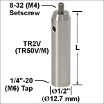
- Constructed of 304L and 316 Stainless Steel for Vacuum Applications
- One 8-32 (M4) Tapped Hole on Top and One 1/4"-20 (M6) Tapped Hole at Base
- Removable 8-32 (M4) Threaded Setscrew
- Available in Lengths Ranging from 3/4" to 3" (20 mm to 75 mm)
- We Also Offer a Complete Line of Standard Ø1/2" Posts
These nonmagnetic, vacuum-compatible stainless steel posts are precision ground to Ø1/2" (Ø12.7 mm). One end has a 1/4"-20 (M6) tapped hole, while the other end has a removable, 8-32 (M4) threaded setscrew (5/64" [2 mm] hex). A side-located Ø0.13" (Ø3.1 mm) hole is bored straight through the post; a balldriver can be inserted through the hole to provide extra leverage when tightening mounted components. This hole also serves to vent the 8-32 (M4) threaded hole. The 1/4"-20 (M6) hole in the bottom of the post is not vented, so we recommend using a vented cap screw.

- Mount Ø1/2" Post Holders and Other Components to an Optical Table or Breadboard
- Vacuum-Compatible Design (>10-6 Torr)
- Double Vacuum Bagged for Cleanroom Environments
- Same Stability and Footprint as Our Standard Mounting Bases
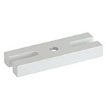
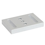
These vacuum-compatible bases are similar to our standard mounting bases, which allow post holders to be secured to an optical table in a variety of position. A 3/8" (10 mm) long 1/4"-20 (M6) vented cap screw (SH25S038V for imperial or SH6MS10V for metric) is recommended for attaching post holders to our mounting bases.

| Specifications | |
|---|---|
| Vacuum Compatibility as Packageda |
>10-6 Torr |
| Materials | 2024-T3 Aluminum |
| Preparation and Packaging |
Chemically Cleaned and Double Vacuum Bagged |
| Aluminum Outgassing Rate at 20 °C |
7.6 x 10⁻⁹ Torr-Liters/s/cm2 |
| Maximum Torque | 28 in·lbs (3.2 N·m) |
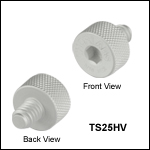
The TS25HV and TS6HV/M are 1/4"-20 or M6 x 1.0-threaded for compatibility with our imperial or metric Vacuum-Compatible Ø1/2" Post Holders, respectively. Please note that we do not recommend using an L wrench hex key to tighten these thumbscrews, as this may break off the screw head. The recommended maximum torque is 28 in·lbs (3.2 N·m). We also offer standard spring-loaded thumbscrews.

TS25HV Drawing
 Products Home


 Zoom
Zoom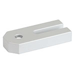
 Vacuum-Compatible Ø1/2" Post System