 Products Home / Polarization Optics / Wave Plates and Variable Retarders / Variable Wave Plates / Pockels Cells
Pockels Cells
- Voltage-Controlled Wave Plate
- KD*P Electro-Optic Crystal
- Ideal for Q-Switching
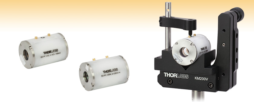
EO-PC-550
EO-PC-1064
EO-PC-550 in KM200V Mount
(Mount Sold Separately)


Please Wait
| Item # | EO-PC-550 | EO-PC-850 | EO-PC-1064 |
|---|---|---|---|
| Wavelength Range | 425 - 700 nm | 700 - 1000 nm | 1064 nm |
| Design Wavelength | 532 nm | 785 nm | 1064 nm |
| Aperture | Ø9.5 mm | ||
| Clear Aperture | Ø9.0 mm | ||
| Transmission | >99% | ||
| Half-Wave Voltage | 3.3 kV @ 532 nm | 5 kV @ 800 nm | 6.6 kV @ 1064 nma |
| Extinction Ratiob | >250:1 | >550:1 | >1000:1 |
| Capacitance | 8 pF | ||
Features
- 3 Wavelength Range Options:
- 425 - 700 nm
- 700 - 1000 nm
- 1064 nm
- Longitudinal Pockels Cell
- Wedged Windows for 0° Offset and Minimal Back Reflection
Thorlabs' Pockels Cells offer fast, precise control of the output light's polarization direction as a function of applied voltage. They can be thought of as voltage-controlled wave plates. Our family of Pockels cells uses a potassium di-deuterium phosphate (KD*P) crystal with the electric field applied in the longitudinal direction. Using the longitudinal orientation causes the drive voltage to be independent of aperture size, thus allowing for larger apertures than can be realized in a transverse Pockels cell. Since the response is much faster than standard acousto-optic or liquid crystal devices, Pockels cells are ideal for Q-switching lasers. Our Pockels cells utilize wedged windows to ensure 0° offset and to minimize back reflections. The windows are AR coated for 425 - 700 nm, 700 - 1000 nm, or 1064 nm.
The Pockels cell is an electro-optic device (much like an electro-optic modulator) that consists of an electro-optic crystal through which light is transmitted. The polarization direction of the light is controlled by the voltage applied to the crystal. The Pockels Effect explains the behavior of the Pockels cell: an applied constant or variable voltage (electric field) to the crystal produces linear changes in the birefringence of the crystal (in contrast to the Kerr Effect, which is quadratic with E). Applying a constant voltage allows the Pockels cell to operate as a voltage-controlled wave plate. By applying a variable voltage, one can use a Pockels cell to vary the phase delay through the crystal. Pockels cells are essential components in various optical devices such as Q-switches for lasers and electro-optical modulators.
We recommend a drive voltage no greater than 6 kV, as excessive voltage can damage the crystal. The recommended maximum modulation frequency for these K*DP crystal Pockels cells is 5 kHz. Although the cells can be driven up to 20 kHz, they experience piezoelectric ringing at frequencies beyond 5 kHz. We do not recommend driving at these frequencies unless this ringing is acceptable in your application. For general use, a power supply capable of up to 5 kHz modulation and 5 - 6 kV output is recommended. For applications such as Q-switching, fast rise times (on the order of 50 ns) are desired and the user should ensure that his or her power supply is capable providing such fast rise times. To create the electrical connections, these Pockels cells have two electrical sockets for 1 mm pins. Please note that Thorlabs does not currently offer Pockels cell drivers.
Handling Note
Thorlabs' Pockels cells should not be disassembled under any circumstances. These extremely sensitive devices are precisely aligned in an ultra-clean environment by skilled technicians. The only approved cleaning method is the use of dry nitrogen to blow off external dust. Please contact Tech Support if you suspect the cell is damaged or contaminated.

Click to Enlarge
We do not recommend applying a voltage greater than 6 kV. If half-wave retardance is desired at 950 nm and above, we recommend setting the Pockels cell to act as a quarter-wave plate in a double-pass beam geometry.


The shaded regions in the graphs below denote the spectral ranges over which we recommend using these Pockels cells.


| Posted Comments: | |
Maria Romodina
(posted 2020-09-10 14:04:55.39) I want to use this Pockels cell to control the laser beam with 800 nm wavelength and 40 fs duration of the pulses. How big is dispersion of crystal in the pockels cell? How long will be the pulse after the pockels cell? YLohia
(posted 2020-09-24 03:38:04.0) Hello, thank you for contacting Thorlabs. The KD*P crystal in this Pockels Cell is 20 mm long. So the dispersion from the crystal will be: 35.0 fs^2/mm x 20 mm = 700 fs^2.
The cell also contains 2 fused silica windows of 6.25 mm total thickness. The dispersion from this component is thus: 36.0 s^2/mm x 6.25 mm = 228.6 fs^s.
The total for cell is therefore ~929 fs^2. Your 40 fs pulse at 800 nm after traveling through cell will expand to 64 fsec. Maria Romodina
(posted 2020-09-09 15:50:05.2) Hi, could you please send me recommendations for drivers. Thanks YLohia
(posted 2020-09-10 08:47:05.0) Hello Maria, thank you for contacting Thorlabs. I have reached out to you directly with some suggestions for 3rd party drivers. tom tom
(posted 2020-04-27 10:42:51.297) Hello,
I am using a pulsed laser and I would like to know if the pockel cell will work in term of damage threshold? The laser is 2W at 940nm with a repetition rate of 1 Mhz, pulse width of 30 fs and beam diameter of 1.4mm.
Could you also send me recommendations for drivers with the appropriate spec ?
thank you YLohia
(posted 2020-04-27 11:01:45.0) Hello Tom, thank you for contacting Thorlabs. Unfortunately, we do not have a damage threshold value for femtosecond pulses. For reference, an estimate for a CW beam would be 50 W/cm^2 at 1065 nm. The driver selection will be depended on the signal (rep rate and pulse width) you plan on driving the Pockels Cell with. I have reached out to you directly to discuss options for your specific requirements.
That being said, you may want to consider our OM6N (or OM6NH) for your application: https://www.thorlabs.com/newgrouppage9.cfm?objectgroup_id=13672. These modulators are specifically designed for fs sources and introduce minimal disperion (Pockels cell will introduce a significantly higher amount of dispersion). Additionally, the OM6NH will yield much higher extinction ratios. These require only 0-1 V input for control, so they can be driven using standard lab voltage source or function generator without the need for an expensive high voltage driver. Allan McPherson
(posted 2019-10-24 13:04:44.423) I am trying to determine if the EO-PC-850 would be appropriate for a regenerative amplifier I am designing. What would be a typical rise time for this Pockels cell? YLohia
(posted 2019-11-05 02:57:03.0) Thank you for contacting Thorlabs. The Pockels Cell itself should have a picosecond response. These are typically limited by the driver as it is difficult to provide the thousands of volts required in the picosecond regime. danpershin1995
(posted 2019-01-17 04:50:17.52) Hello, could you please answer a few questions about Pockels cell
EO-PC-550?
1. What is the damage threshold? Is it suitable for 10 W 532nm continuous laser (beam diameter is 2 mm - 5 mm)?
2. Can the Pockels cell provide stable light polarization during long period of time (1 minute) if operating voltage is applied?
3. Which driver can you recommend? For my application the rise time should be less then 20 ms.
Regards, Daniil llamb
(posted 2019-02-07 08:07:41.0) Hello Daniil, thank you for contacting Thorlabs. 1. We do not specify a damage threshold for this optic, but you shouldn't see damage below 150W/cm^2, so it should be suitable with your source. 2. The Pockels cell can provide stable light polarization for 1 minute as long as it is operated below 150 W/cm^2. 3. We do not offer/stock any drivers for our Pockels cells at the moment. There are more details in the Overview tab on this webpage in regards to a suitable driver. j65ren
(posted 2018-07-19 13:19:39.86) why the pockels cells are limited at 5 kHz operation frequency while Thorlabs' EOM goes up to 100 MHz, I need to modulate my 830nm laser polarization at around 40 Mhz , can I use your EOM ? any drivers up to that specs? YLohia
(posted 2018-07-20 04:19:53.0) These pockels cells require significantly higher drive voltages (on the order of 5kV) and the driver must withstand the doubled voltage returned to it due to ringing. The recommended maximum modulation frequency for these K*DP crystal pockels cells is 5 kHz, though the cells can be driven up to 20 kHz. We do not recommend driving at these higher frequencies unless this ringing is acceptable in your application. We recommend the EO-PM-NR-C1 for your application. Unfortunately, our HVA200 modulator driver can only support up to 1 MHz modulation rate. ademir.aleman
(posted 2018-07-18 22:21:05.947) Dear,
What is the damage threshold for this pokels cell?. For my application I use a 1.5mW cw laser at 660nm, Spot size is 1mm2. YLohia
(posted 2018-07-19 09:45:13.0) Hello, thank you for contacting Thorlabs. While we have not tested these parts for a Damage Threshold, you will not damage the pockel cell with a 1.5 mW, 1mm beam. tom.dzelzainis
(posted 2018-07-04 13:44:40.337) I have a question. Can I use the 1064nm cell at 1030nm? Why is the recommended range for this model some narrow?
Many thanks,
Tom. YLohia
(posted 2018-07-09 09:39:25.0) Hi Tom, in general, that cell can be used for 1030nm, though the AR coating is specifically designed for 1064nm. Please see the transmission plot for the cell here (https://www.thorlabs.com/images/TabImages/EO-PC-1064_Transmission_800.gif) and the AR coating reflectance plot here (https://www.thorlabs.com/images/tabimages/Standard_1064nm_V_ARC_G1-780.gif). There will be some loss at 1030nm, but the cell will still work. Ed.Miesak
(posted 2018-02-06 15:03:31.463) Can your Pockels cell take a 50G shock without being damaged? Regards, Ed Miesak tfrisch
(posted 2018-02-13 10:59:40.0) Hello, thank you for contacting Thorlabs. These pockels cells are not designed for rugged applications, and unfortunately, we don't have the capability to test them for impact. I will reach out to you directly to discuss you application and if there is any data we might be able to offer that could help you estimate a maximum impact. dustinkleckner
(posted 2017-07-21 08:47:07.32) What is the damage threshold for a 532nm CW laser? I have a 20W beam in ~ 1mm spot, and I was wondering if I could use this Pockels cell. nbayconich
(posted 2017-07-31 08:23:08.0) Thank you for contacting Thorlabs. The damage threshold of these pockels cells is 50 W/cm^2 (CW) at 1065nm. A techsupport representative will contact you directly with more information. florent.haiss
(posted 2017-07-20 11:19:47.1) Hi, could you please send me recommendations for drivers. Thanks. tfrisch
(posted 2017-07-26 02:20:46.0) Hello, thank you for contacting Thorlabs. While we don't have a recommended driver model, I can reach out to you with contact information for some vendors our customer have used in the past for pockels drivers. dv
(posted 2017-05-28 22:57:51.96) I am looking for a pockels cell for 1064nm, 8ns pulse width, 4KHz PRF, and 10mJ pulse energy. Your product _STANDS_OUT_ in terms of optical efficiency (>99% !!), which is my _#1_ priority. Does your product employ optic windows external to the KDP crystal? (I.e., is it just the bare crystal exposed on both surfaces, or is it paneled with wedged optic windows with liquid matching layer?). In addition, my application is purely pulse-redirection - I am NOT concerned with fempto or other spectral broadening effects due to piezoelectric phenomenon. However it IS IMPERATIVE that beam quality be maintained as I am using this to pump several cascaded nonlinear optics downstream. I will be requiring half-wave retardation, however requisite excitation amplitude, and requisite electronic slew rate, is of no concern (our capabilities are beyond what's needed). Rather I need to know whether your product will survive repeatable excitations driving it to full half-wave retardation. You can assume we will precisely [and repeatably] be driving it to ThorLabs specified 6.6KV. If performance can be guaranteed, we would immediately be purchasing 2 units for our initial prototype, and then (upon successful long-term operational demonstration), intend to incorporate your product into our mass production model, via a company previously spun-off from my university employer.
Thank you for your assistance, and feel free to contact me with any questions you may have about my application.
Don V tfrisch
(posted 2017-06-21 03:28:59.0) Hi Don, thank you for contacting Thorlabs. It looks like you've already been in contact with our Tech Support group, but I'll reach out to you directly as well to highlight a few points. The pockels cell does have wedged windows and the given transmission curves are for the entire unit, not just the KDP. I can reach out to you more about the details of your application, but note that for 1064nm where the halfwave voltage is greater than 6kV (around 6.6kV), it is safer to configure the cell to run at a quarter wave and use a double pass geometry. weld
(posted 2017-03-23 15:46:17.033) What is the optical damage threshold for the 1064nm-coated Pockels cell? We would like to use 20 Watts in about a 1mm beam diameter. Thank you. tfrisch
(posted 2017-03-30 10:29:54.0) Hello, thank you for contacting Thorlabs. I will reach out to you about the details of your laser. psota
(posted 2017-02-14 18:16:27.953) Hello, please, could you recommend me a suitable driver for the Pockels cell?
Regards,
Pavel tfrisch
(posted 2017-02-16 01:42:14.0) Hello, thank you for contacting Thorlabs. While we do not offer a driver in our own catalog, I can reach out to you directly with some ideas on where to look for one. parksj003
(posted 2016-12-01 11:19:45.787) Hello,
I am interested in purchaning the Pockels Cells right after Femto-second laser to modulate the outpout beam polarization. From your overview tab for this item, your company does not seem to provide the Pockels cell drivers. Would you recommend proper one if you don't mind?
Best,
Seongjun tfrisch
(posted 2016-12-01 08:27:54.0) Hello. Thank you for contacting Thorlabs. I will contact you directly with advice for driving Pockels Cells. julian.robertz
(posted 2016-10-20 17:25:52.37) Dear Thorlabs,
Is it possible to use one of those pockels cells with 405nm cw lasers as a variable waveplate from 0.0 to 0.5 waves?
Thank you for your answer! jlow
(posted 2016-10-21 04:53:29.0) Response from Jeremy at Thorlabs: We do not recommend using this at 405nm. The liquid crystal retarder, LCC1111-A, could possibly work for your application. I will contact you directly to discuss about the requirements of your application. lymee4949
(posted 2016-08-23 23:15:11.317) Can you please provide the rise time response of each of the pockel cell namely;
EO-PC-550
EO-PC-850
EO-PC-1064
Looking to see if they can handle 10ns rise time or better. Thank you. user
(posted 2016-03-23 08:53:16.097) Can I use this one as an amplitude modulator for "CW" laser? I know EO-AM-NR series are more suitable for the purpose. However, for some reason, it would be great if I can use this one instead of EO-AM-NR series. Is there any problem, like temperature-dependent performance?
And another question, what's happen if we apply low voltage high frequency signal beyond 5 khz (say, 300 V, 20kHz)? Would it be damaged? or not working properly? besembeson
(posted 2016-03-25 10:14:56.0) Response from Bweh at Thorlabs USA: Yes this can also be used for amplitude modulation when used in conjunction with a pair of polarizers. If your application requires fast rise times, then Pockels cells are suitable but the voltage requirements are typically very high (kV) so a suitable high power driver is needed. Please contact me at techsupport@thorlabs.com for information about 20kHz drive frequency, temperature dependence and driver recommendations. rasha
(posted 2014-05-14 10:22:04.29) The pockels cell controls the output polarization as a function of applied voltage. Can you please give me more details on how it changes the polarization? Let’s say we have a certain polarization state at the input, does it pass the light through a 0 degree polarizer then generates the required polarization? Or does it shift the input polarization a specific value which depends on the applied voltage? Also, do the pockels cells that you have operate in FSO or fiber? besembeson
(posted 2014-06-12 05:17:07.0) A Response from Bweh at Thorlabs: This is based on the electro-optic effect, whereby a birefringence is induced as a result of an applied constant or varying voltage. The phase changes created is linearly dependent on the applied voltage. The birefringence induced by the applied voltage creates a fixed phase shift between the ordinary and extraordinary rays that leads to a rotation of the electric field vector. There are a few publications online that describe this further, for example: http://www.lasermetrics.com/pdf/pcp.pdf
There is a fixed voltage that provides half wave retardation or quarter wave retardation for a given wavelength. In the case of a half wave voltage, linearly polarized input will be rotated whereas for a quarter wave voltage, a linearly polarized input will become circularly polarized and vice versa. On the following link, under the "Graphs" tab, we have the plots that show these voltages for our pockels cells: http://www.thorlabs.com/newgrouppage9.cfm?objectgroup_id=6149&gclid=CNmk-ICgp74CFUpp7AodTyMAFQ
Our Pockel cells are for free space applications. If you have a fiber source, we have an extensive line of fiber collimators. We also have liquid crystal retarders that you may look into for your application. These have much slower response compared to pockels cells though: http://www.thorlabs.com/navigation.cfm?guide_id=2258 carlo.alonzo
(posted 2013-08-29 14:51:47.737) We are interested in using this as a modulator in our multiphoton microscope, but are not sure where to begin our search for an appropriate driver. Would you be able to give some suggestions? tcohen
(posted 2013-09-05 16:22:00.0) Response from Tim at Thorlabs: Thank you for contacting us! We are currently in the process of designing a driver. We’ll contact you to discuss this further and possible options in the interim. |