 Products Home / Motorized Stages / Motorized Rotation Stages and Mounts / Rotation Mount with Resonant Piezoelectric Motors
Rotation Mount with Resonant Piezoelectric Motors

- SM1-Threaded Rotation Mount with Closed-Loop Positioning
- Open Frame Design for OEM Applications
- Control via Interface Board, GUI, or ASCII Message Calls
- Fully Integrated Drive Electronics
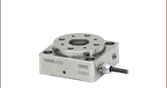
ELL14K
Rotation Mount Bundle
(Mount and Board Included)
Rotation Mount for Ø1" or Ø25.0 mm Optics
(Also Available Individually)
Interface Board
Application Idea
The ELL14K rotates a mounted, SM1-threaded polarizer within a 60 mm cage assembly.
ELLB
Bus Distributor


Please Wait
| Key Specificationsa | ||
|---|---|---|
| Travel (No Limit Switches)b |
360° Continuous | |
| Homing Repeatability | 4.36 mrad (0.25°) | |
| Bidirectional Repeatability | 873 µrad (0.05°) | |
| Velocity (Maximum) | 430 °/s | |
| Maximum Total Load | 50 g (1.76 oz)c | |
| DC Voltage Input | 4.5 to 5.5 V | |
| Weight of Mount | 80 g (2.82 oz) | |
| Minimum Lifetime | 100 km (>600 000 Revolutions) | |
| Mount Dimensions |
66.0 mm x 82.5 mm x 19.0 mm (2.6" x 3.25" x 0.75") |
|

Click to Enlarge
The components of the ELL14K Rotation Mount Bundle are shown connected and with key features labeled.
 Thorlabs' Elliptec Technology for OEM
Features
- Ideal for OEMs and Applications Requiring Rapid and Precise Optic Rotation
- Micro-B USB and Picoflex®1 Connectors for Control Signals
- Multi-Drop Serial Communication Protocol Supported
- SM1-Threaded Rotation Mount for Ø1" or Ø25.0 mm Optics
- Absolute Home Position Found with Infrared and Magnetic Sensor Technologies
- Magnetic Encoder Used to Position Mount
- Bus Distributor Facilitates Control of up to Four Elliptec Devices
Driven by Thorlabs' Elliptec™ piezoelectric resonant motor technology, this rotation mount is designed to be a compact solution for applications requiring optic rotation. Thorlabs offers the ELL14K rotation mount bundle, which contains the ELL14 rotation mount, an interface board for manual control of the mount, power supply, and cables for connecting the mount and interface board to each other and to a PC. The ELL14 can also be purchased separately.
The rotating cell of each mount is internally SM1 (1.035"-40) threaded and includes two SM1RR retaining rings for mounting Ø1" or Ø25.0 mm optics. It is designed to be lightweight and compact, and the closed-loop operation provides rotation to specified orientations with a repeatability of 873 µrad. The assembled components of the ELL14K are shown in the image to the right, with key features labeled. Please see The Elliptec™ Motor tab for more information.
The motors are highly dynamic and have no gearing. The tips of both motor housings are in firm contact with the plastic track at the base of mount, as can be seen in the image at the right. The motors are installed with opposite orientations and translation in both directions occurs when one motor pushes the track forward while the other pulls it backward. The rotation mount is not designed for continuous operation. We recommend operation with duty cycles of 40% or less. When power is not applied to the motors, the stage is held in place by an approximately 0.01 N·m combined torque exerted by the stationary arms of the motors.
The open frame format, versatility, and simplicity of this rotation mount makes it attractive for OEM applications, as it can be customized according to customer requirements and produced in high-volume quantities. Please contact us to discuss your specific requirements so that we may tailor a solution to meet the needs of your application.
Control
There are multiple options for powering, driving, and controlling this rotation mount, which are detailed in the Positioning the Rotation Mount section of the Operation tab. The mount possesses a 3.3 V serial bus and is designed to be operated with or without the interface board; the Pin Diagram tab provides pin assignments. Thorlabs offers software for our Elliptec products capable of providing full and independent control of the mount. When the interface board is used as an accessory to change the position of the mount, its status in the software is automatically updated.
| Elliptec Resonant Motor Products | ||||
|---|---|---|---|---|
 |
 |
 |
 |
 |
| Multi-Position Sliders | 28 mm Linear Stage | 60 mm Linear Stage | Rotation Stage | Rotation Mount |
Multiple Elliptec devices can be controlled using the ELLB Bus Distributor or by splicing multiple connectors onto one ribbon cable. A single bus distributor can connect up to four Elliptec devices; up to 16 devices can be connected if the buses are daisy chained. This bus can be controlled one of three ways: through an interface board (included with the bundles below) to connect to a PC running the Elliptec software, by connecting to an Arduino®2 or Raspberry Pi®3 board, or by wiring the connector pins to a user-supplied control board. Alternatively, up to 16 devices can be spliced onto a single ribbon cord. The devices can then be simultaneously controlled by the interface board or selectively controlled by the Elliptec software. See the manual for instruction on how to splice multiple devices onto a ribbon cord and the Pin Diagrams tab for pin assignments when making custom connections.
- Picoflex is a registered trademark of Molex Incorporated.
- Arduino is a registered trademark of Arduino Sa Société Anonym (SA).
- Raspberry Pi is a registered trademark of the Raspberry Pi Foundation.
| Specificationsa | |
|---|---|
| Performance | |
| Travel | 360° Continuousb |
| Maximum Speedc | 430 °/s |
| Bidirectional Repeatabilityd | 873 µrad (0.05°) |
| Homing Repeatability | 4.36 mrad (0.25°) |
| Bidirectional Accuracye | 6.98 mrad (0.4°) |
| Backlash | 226.9 µrad (0.013°) |
| Encoder Resolution (Relative Magnetic Encoder) | 143360 counts/rev (43.8 µrad/count) (0.0025°/count) |
| Minimum Incremental Motion | 34.9 µrad (0.002°) |
| Minimum Holding Torque (Both Motors Engaged) | 0.01 N•m |
| Axis Wobblef | 244.3 µrad (0.014°) |
| Maximum Total Loadg | 50 g (0.11 lb) |
| Minimum Lifetimeh | >600 000 Revolutions (100 km) |
| Electrical | |
| Motor Type | Elliptec Resonant Piezo |
| DC Voltage Input | 4.5 to 5.5 V |
| Typical Current Consumption, During Movement | 800 mA |
| Typical Current Consumption, During Standby | 50 mA |
| Communications | |
| Bus | Multi-Drop 3.3 V/5 V TTL RS232 |
| Connector on Rotation Stage Board | Picoflex® |
| Connectors on Interface Board | Picoflex®, Micro USB, DC Jack [6.3mm OD (GND), 2.1mm ID (+5V)] |
| Speed | 9600 baud |
| Data Length (1 Stop Bit, No Parity) | 8 bit |
| Protocol Data Format | ASCII HEX |
| Module Address and Command Format | Mnemonic Character |
| Mechanical | |
| Mounting Thread | SM1 |
| Dimensions of the Rotation Mount Board | 66.0 mm x 82.5 mm x 19.1mm (2.6" x 3.25" x 0.75") |
| Weight of Rotation Mount Board | 80 g (0.176 lb) |
| Environmental Operating Conditions | |
| Temperature Range | 15 to 40 °C (59 to 104 °F) |
| Maximum Relative Humidity (Non-Condensing) | <80% at 31 °C |
| Maximum Altitude | 2000 m |

Click to Enlarge
Components of the ELL14K Bundle
(One Region-Specific Power Adapter Included with the Power Supply)

Click to Enlarge
Mechanical Drawing of the Rotation Mount
For more information on mounting options see the Operation tab.

Click to Enlarge
Mechanical Drawing of the Interface Board
| Connector J1 Pinouta | ||
|---|---|---|
| Pin | Type | Function |
| 1 | PWR | Ground |
| 2 | OUT | OTDX - Open Drain Transmit 3.3 V TTL RS232 |
| 3 | IN | RX Receive - 3.3 V TTL RS232 |
| 4 | OUT | In Motion, Open Drain Active Low Max 5 mA |
| 5 | IN | JOG/Mode, Active Low Max 5 V |
| 6 | IN | BW Backward, Active Low Max 5 V |
| 7 | IN | FW Forward, Active Low Max 5 V |
| 8 | PWR | VCC +5 V ±10%; 800 mA |

Click to Enlarge
Pinout diagram of the Picoflex® connector is shown referended to a partial diagram
of the ELL14 Rotation Mount Board.
| ELLB Connector J1, J2, J3, and J4 Pinouta,b | ||
|---|---|---|
| Pin | Type | Function |
| 1 | PWR | Ground |
| 2 | OUT | OTDX - Open Drain Transmit 3.3 V TTL RS232 |
| 3 | IN | RX Receive 3.3 V TTL RS232 |
| 4 | OUT | In Motion, Open Drain Active Low Max 5 mA |
| 5 | IN | Not Connected |
| 6 | IN | Not Connected |
| 7 | IN | Not Connected |
| 8 | PWR | VCC +5 V ± 10%; 800 mA per Connected Device |

Click to Enlarge
Pinout diagram of the Picoflex® connector is shown referenced to a simplified diagram
of the ELLB Bus Distributor. The polarity indicator on the connector
must be adjacent to the red wire on the supplied 8-connector cables.
Operation Notes
This tab contains information on handling, mounting, and operating the ELL14K Rotation Mount Bundle.
Contents- Handling
- Mounting and Loading the Rotation mount
- Supplying Power
- Operation of the Motors
- Homing the Rotation mount
- Positioning the Rotation mount
- Resonance Frequencies

Click to Enlarge
The Rotation Mount, Back

Click to Enlarge
The Rotation Mount, Front
Handling
The rotation mount and interface board included in the ELL14K bundle are robust to general handling. To ensure reliable operation, keep the surface of the plastic track contacted by the motors free of oils, dirt, and dust. It is not necessary to wear gloves while handling the rotation mount, but avoid touching the track to keep it free of oils from fingerprints. If it is necessary to clean the track, it may be wiped with isopropyl alcohol or mineral spirits (white spirit). Do not use acetone, as this solvent will damage the plastic track.
The open frame format of the ELL14 can tolerate up to 8 kV of static discharge. ESD precautions should be taken, as an electrostatic discharge can produce an electrical signal that may cause an unintended movement of the mount. A bending load in excess of 500 g applied to the board may cause the PCB to deform, which will degrade the performance of the rotation mount. As readings from a magnetic sensor are used during the homing and positioning of the mount, avoid subjecting the structural PCB to excessive loads or magnetic fields. Limit the strength of magnetic fields in proximity to the magnetic sensor to ±5 mT to avoid negatively affecting the homing and positioning operations.
Mounting and Loading the Rotation Mount
The rotation mount may be mounted either vertically or horizontally. The Elliptec motors should be facing up if the mount is used horizontally. The mount has several mounting features that can be used with Thorlabs components or within a custom OEM assembly. Four Ø0.12" (3.0 mm) through holes are spaced 60 mm apart and provide compatibility with our 60 mm cage system. These holes can pass 4-40 or M3 screws for mounting to custom structures. Additionally, there are four Ø4.2 mm (Ø0.17") through holes spaced 50 mm apart which can be used with 6-32 or M5 screws for custom mounting. The back of the mount features four Ø4.0 mm (0.16") holes 30 mm apart with locking M3 setscrews for use with our SR-Series cage rods. A 1.5 mm hex key comes with the mount for locking these screws. SR-Series cage rods can be used to attach the ELLA1 adapter to allow for post mounting or to attach ER-Series cage rods for integration into a 30 mm cage system. The images below show three mounting options.

Click for Details
The rotation mount can be mounted in a 60 mm cage system by sandwiching the PCB between two cage rods using the Ø0.12" (3.0 mm) holes in the corners.

Click for Details
The rotation mount can be adapted to a 30 mm cage system using SR025 cage rods in the Ø0.16" (4.0 mm) holes on the back of the mount.

Click for Details

Click to Enlarge
Features of the Rotation Mount
The maximum allowed weight of the mounted optic is 50 g. The load must be centered on the mount in order to acheive 50 g. In all cases of mounting and loading, ensure that nothing interferes with the moving parts of the rotation mount and that the mount and its load are securely fastened to prevent jostling during movement. Jostling of the stage or the load can cause an encoder error.
Supplying Power
When the setup includes the interface board, power may be supplied through the Micro-B USB connector and/or the 5 VDC power socket located on the board. The electronics on the interface board convert the applied DC signal to a sinusoidal signal oscillating at the required resonance frequency.
The ELL14K bundle includes a 5 VDC power supply whose connector mates with the power socket on the interface board. Delivering power through this socket also allows the Micro-B USB connector to be used for a computer to control the mount remotely. The power supplied by a computer through the USB 2.0 connection is not sufficient to power the mount. If computer control is not necessary, another option for supplying power to the mount is a portable USB 5 V battery pack connected to the Micro-B USB connector on the interface board.
When the implementation does not include the interface board, the connection with the power source is made using the pins on the Picoflex® connector that is included on the rotation mount board. A pinout diagram of this connector is included in the Pin Diagram tab, and information on powering and addressing the rotation mount is given in the manual and the communications protocol manual, respectively.
Operation of the Motors
The motion of the rotation mount is controlled by forcing the piezoelectric elements to vibrate at specific ultrasonic frequencies. For each motor, there is one ultrasonic resonant frequency that will push the mount forward, and another that will pull the mount backward. Operating a motor at one of its resonance frequencies causes the tip of the motor to continuously cycle in a tight clockwise elliptical path. When the motor is driven at its other resonant frequency, the tip of the motor cycles through that same path in a counterclockwise direction. Both resonant frequencies are around 100 kHz. The total displacement at the tip of motor is a function of the mechanical load it is driving and the voltage supplied to the piezo element. In the case of no loading and a 5 V maximum driving voltage at a resonant frequency, the tip of the motor expands and contracts no more than a few microns while tracing the elliptical path. Please see The Elliptec™ Motor tab for more information and an animation illustrating the operational principle of the motors.
Homing the Rotation Mount

Click to Enlarge
The Interface Board

Click to Enlarge
Features of the Interface Board
To Home the mount, press the BW button on the interface board, click the Home button in the Elliptec software's graphical user interface (GUI) or send the appropriate ASCII message as is specified in the communications protocol manual.
The default Home position is referenced to a fixed feature on the mount assembly. If desired, the user may redefine the position of Home to be offset from the default position by up to +90° (a quarter turn in the clockwise direction). Being able to customize the Home position can be useful when synchronizing the orientations of two or more mounts. When executing the Home command, the mount first finds the approximate location of Home, and then a fine-positioning procedure is used to orient the mount at Home with an accuracy of 288.0 µrad. The user can specify whether the mount rotates in a clockwise or counterclockwise direction (as defined from the perspective of looking down on the surface of the mount) during the first phase of the homing procedure, but the fine-positioning phase is always performed in the counterclockwise direction for repeatability.
Positioning the Rotation Mount
Note that the rotation mount is not intended for continuous operation. We recommend operation with duty cycles of less than 40% during general use, while operation with duty cycles greater than 60% should be limited to a few seconds.
Before the mount may be positioned, the Home position of the mount must be found. Please see the previous section for details. The movement of the mount may be controlled through computer control via the Elliptec™ software package that may be downloaded, or by sending simple signals to digital lines on the mount's board. A link to download the software and accompanying documentation can be found in the Software tab.
Multiple Elliptec devices can be be controlled using the ELLB Bus Distributor or by splicing multiple connectors onto one ribbon cable. A single bus distributor can connect up to four Elliptec devices; up to 16 devices can be connected if the buses are daisy chained. This bus can be controlled one of three ways: through an interface board (included with the bundles below) to connect to a PC running the Elliptec software, by connecting to an Arduino® or Raspberry Pi® board, or by wiring the connector pins to a user-supplied control board. Note that if an interface board is used, its on-unit buttons will be disabled. Alternatively, up to 16 devices can be spliced onto a single ribbon cord. The devices can then be simultaneously controlled by the interface board or selectively controlled by the Elliptec software. See the manual for instruction on how to splice multiple devices onto a ribbon cord and the Pin Diagrams tab for pin assignments when making custom connections. The communications protocol manual describes how to use the software to individually address each connected device. A link to download the software and accompanying documentation can be found in the Software tab.
The default increment to move the mount forward and backward is 45°, and a custom increment can be set using the Elliptec software or by sending the appropriate ASCII message(s) as specified in the communications protocol manual. The Elliptec software can be used to move the mount to absolute and relative positions, in addition to jogging the mount forward or backward. The software is also used to set the jog step size, read the position of the mount, and adjust the position of Home, as is described in the previous section.
Readings from the magnetic sensor, which can resolve angular increments of 23.8 µrad, are used to position the mount and when executing the Home command. The travel range of the mount is not limited, but the reported orientation of the mount is always expressed as a value between 0° and 359.99°. The minimum incremental movement of the mount is 34.9 µrad, and it can be positioned with a repeatability of 873 µrad in response to signals from the magnetic sensor.
The mount learns to efficiently position itself precisely using a position error compensation algorithm. After the mount moves into a new position, it detects the error between the requested and actual positions. The position of the mount is then corrected, and an error compensation value is calculated. The algorithm is then updated with the error compensation value, so that it is applied when the mount is move to its next position. Typically, an optimum error compensation value is found after between two and six movements.
Resonance Frequencies
On power-up, the factory default setting instructs each motor driving the rotation mount to search for the resonance frequencies that will deliver the best performance. During this process, the rotation mount will translate a forward and backward by a small amount. If movement on start-up is undesirable, it is possible to disable this calibration procedure by using the serial port to initialize the frequencies on power-up. A new search for optimal resonance frequencies may be performed at any time; to maintain optimal performance, it is recommended that new searches be performed after changes in loading and/or ambient temperature. Please see the manual for details.

Click to Enlarge
The Components of the Elliptec Motor

Click to Enlarge
The Elliptec Piezoelectric Resonant Motor
The Elliptec™ Piezoelectric Resonant Motor
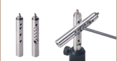
Thorlabs' Elliptec™ piezo resonant motor, shown at right, is lightweight, with a mass of 1.2 g, and compact: the dimensions of the resonator housing, excluding the spring, are 8 mm x 4 mm x 20 mm.
Components of the Motor
The components that compose the motor are shown at far-right. The piezoelectric element is press fit into the aluminum resonator, which has been precisely designed and machined to produce the desired elliptical motion at the tip and to interface optimally with the driven module. The free ends of the spring are integrated with the resonator housing. The wires, which are soldered to the top and bottom of the piezoelectric element, deliver the voltage signal that induces the piezoelectric element to vibrate at ultrasonic frequencies.
When the motor is built into a system, the open loop of the spring is bolted to a sturdy surface that is stationary with respect to the item to be driven, and the tip of the resonator is placed in contact with the item. The purpose of the spring is to maintain constant contact between the tip of the resonator and the driven item, and the direction of motion is determined by the resonance frequency at which the piezo element is driven.
Elliptical Motion and Comparison with Conventional Motors
The motor is operated by driving it at one of its two resonance frequencies. A voltage signal oscillating at an ultrasonic frequency is applied to the piezoelectric chip, which responds by expanding less than a micron and then contracting back to its original dimensions at the frequency of the driving signal. This rapid-cycling change in the chip's dimensions causes a vibration in the aluminum resonator housing. When the vibration is at one of the housing's resonance frequencies, a pushing motion results at the tip of the motor. When the vibration is at the other resonance frequency a pulling motion results.
As illustrated in the video, the pulling and pushing motions result from the tip of the motor tracing an elliptical path in space when the motor operates at resonance. The selected resonance frequency controls the direction of the cyclical motion. The motor's tip traces one half of the ellipse as it expands and the other half as it contracts. When the motor pushes the driven item, the motor's tip is in contact with the item while the tip expands; the two are not in contact while the tip contracts. The converse is true when the motor pulls the driven item in the opposite direction. The total displacement at the tip of the motor is a function of both the mechanical load it is driving and the voltage supplied to the piezo element. The maximum displacement can be up to a few microns when the peak driving voltage is 5 V.
The motor behaves in many ways like a DC or electromagnetic stepper motor, but it does not suffer from many of the drawbacks of these conventional motors. Unlike conventional electromagnetic motors, which must overcome inertial delays to come to a stop, the highly dynamic Elliptec motor can stop within microseconds. As it has no gears, it does not exhibit backlash. Since it possesses no magnets, it is compatible with use in environments sensitive to electromagnetic interference. The motion of the driven element is continuous and smooth. As the tip of the motor must be in contact with the driven item to induce motion, the motor possesses the safety feature of an inherent friction brake. When in contact with a plastic surface, the motor operates virtually silently.
For OEM applications, the motor can be manufactured in volume at low cost, and it can be driven by inexpensive analog electronics. It does not require microprocessors or software; however it is compatible for use with them.

Click to Enlarge
The Elliptec Piezoelectric Resonant Motor Control Software GUI
Software for Devices Driven by Elliptec™ Piezoelectric Resonant Motors
All devices based on the Elliptec™ resonant piezo motor may be controlled by the Elliptec system software, which features an intuitive graphical user interface (GUI). The source code, in C# format, is included in software bundle available for download, and custom applications can be created in any language. The image at right shows a screen capture of the GUI, and the button that follows links to the download page.
Commands are entered in the Sequencer command / wait order section located at the center-left of the GUI. An example of a sequence of commands that might be sent to the device is "Aho0" to move to the rotation stage at address "A" to the home position in the clockwise direction, and then "Afw" to move the stage at address "A" forward by the jog increment. The command "As1" is used to perform the frequency search that will identify the optimal resonant frequencies, for the current operating conditions, for Motor 1 at adddress "A."
Software
Version 1.5.0
Includes the Elliptec System Software, with an easy-to-use GUI. Also available for download is the Communications Protocol manual, which details the communication commands for the Elliptec software package.
| Posted Comments: | |
Rishav Koirala
(posted 2023-09-13 04:04:49.047) Hello, I recently bought this rotation mount bundle for use in my research application, where I intend to use it in an intensity-stabilization feedback loop with a waveplate, a photodiode, and a laser.
My programming environment is in LabVIEW. I have looked for simple examples online and on the Thorlabs website but there don't seem to be any. Could you please send me some example VIs that interface with the mount PCB let me control it? Much appreciated. Hanjun Koh
(posted 2020-12-25 09:04:26.163) Hi, I am willing to control two rotation ELL14K individually and ELLB bus distributor by using Arduino. Could you send me Arduino examples?
Also I would like to receiving the data from PM101 power meter by using Arduino. Please let me have Arduino example program. cwright
(posted 2021-01-05 10:56:11.0) Response from Charles at Thorlabs: Hello and thank you for your query. You can also contact your local technical support directly using the contact details on our site: https://www.thorlabs.com/locations.cfm
Unfortunately I do not currently have an Arduino available and we do not have ready made examples for these cases but I would suggest looking at the official Arduino serial documentation and using the Serial.readBytesUntil()until the Termination character in the command protocol is reached: https://www.arduino.cc/reference/en/language/functions/communication/serial/
The ELL devices are 5V tolerant so you can use these directly with the Arduino. The command protocol contains the serial parameters and controls which you can use to communicate with the devices.
The Elliptec command protocol can be found at the following link:
https://www.thorlabs.com/Software/Elliptec/Communications_Protocol/ELLx%20modules%20protocol%20manual.pdf
There is a also a guide for using the PM101 with a microcontroller which can be found here: https://www.thorlabs.com/_sd.cfm?fileName=MTN013681-D04.pdf&partNumber=PM101
To use it with an Arduino you would need to switch it to UART mode to be 5V tolerant or use a bidirectional logic level shifter. The Serial Parameters, such as Baud Rate,Data Bits, Flow Control and Termination Character are detailed in this document. The commands you can send are also there.
I will reach out to you in case you have questions. Vincent Forster
(posted 2020-11-20 03:45:25.353) Hi I am willing to control two rotation mounts individually using the same ELLB Bus distributor, could you send me LabView or Python examples please ? cwright
(posted 2020-11-20 08:07:03.0) Response from Charles at Thorlabs: Hello and thank you for your query. We will reach out to you with a couple of examples for using two Elliptec devices. David Barbalas
(posted 2020-11-19 12:05:41.04) Is it possible to get the piezoelectric rotator and the IC control elements separately? We are looking for an in-situ rotation stage for a cryostat sample positioner and would like to be able to separate the piezoelectric drive in the cryostat from the electronics outside. cwright
(posted 2020-11-20 11:25:40.0) Response from Charles at Thorlabs: Hello David and thank you for query. Unfortunately we would not be able to supply the rotation mount separate from the drive electronics for low order quantities as modifications to the boards are something which would require significant R&D. I will reach out to you to discuss your application. user
(posted 2020-09-21 08:18:14.9) Hello, I could not find the LabView example for the ELLO14k on the website, which was helpful to many people. Could I please send me a copy of it as well? cwright
(posted 2020-09-23 03:21:00.0) Response from Charles at Thorlabs: Hello and thank you for contacting us. I have reached out to you by email with an example. Stefano Pirotta
(posted 2020-08-21 23:27:39.55) Dear all, I would like to come back to the question about arduino or raspberry connection.
If I want to connect ELL* motor to arduino: can I directly use the TX and RX pins of arduino to connect to pin 2 and 3 of the 8 way Picoflex male SMD ? Do I need an TTL to RS232 adapter? Arduino is 5V, while ELLx wants 3.3V max: do I need another adapter?
And for the raspberry? Again an adapter is necessary?
Thanks
stefano cwright
(posted 2020-08-26 10:00:00.0) Response from Charles at Thorlabs: Hello Stefano. You do not need an adapter of any kind to use it with the Arduino. These elliptec devices are designed with the 3.3V LV TTL levels in mind but are 5V TTL tolerant. You can connect it directly to the Arduino. For the Raspberry Pi, whose GPIO pins are 3.3V, you could use a logic level shifter but a voltage divider made from a couple of resistors would also work to enable the Rpi to receive messages from the Elliptec module without damage. If you need advice setting this up, or initiating communication with the device,your local technical support team will be able to help. user
(posted 2020-07-01 07:42:04.147) Dear Sir.,
I wrongly bought ELL4 product instead of ELL4k.
Can I now buy the interface board, power supply and cables to ? I cannot find them on you site,
thanks,
regards,
Genni cwright
(posted 2020-07-02 08:42:12.0) Response from Charles at Thorlabs: Hello Genni and thank you for contacting us. Typically when such component items cannot be found on the site, your local technical support team can provide you with a quote for them. I will reach out to you directly about this. Youngchul Kim
(posted 2020-05-31 23:52:33.91) Can I also have a labview example?
I love the item except that the cable needs to point outward, not toward the center (optics area). DJayasuriya
(posted 2020-07-15 07:51:04.0) Thank you for your inquiry. I will get in touch with you directly to send the examples. DJayasuriya
(posted 2020-07-15 07:51:04.0) Thank you for your inquiry. I will get in touch with you directly to send the examples. F-A Bégin
(posted 2020-05-27 14:19:01.76) Hi!
Can the deg/jog value can be set to another value and keep this value even though the ELL14 is shut down. Like setting the default value to 2 or 3 deg instead? Also, can you please sent me the LabVIEW sample VI? DJayasuriya
(posted 2020-06-03 10:01:47.0) Thank you for your inquiry. Yes you would be able to set a default value. You would have to save it using the "USER SAVE" button or send the command "us", i.e. 0us for a unit at address zero "0". We will get in touch with you directly for the LABVIEW VI. Dennis Wilken
(posted 2020-03-17 17:28:31.597) I want to program some ELL14 rotation stages. My start, however, was a bit bumpy.
The programming guide doesn't feel userfriendly. I would prefer some less cryptic headings. Why do you use headings like "_DEVGET_INFORMATION" is this some kind of standard that I don't know of? The commands seem to be in random order. To find the commands I need, I had to scroll through the whole document.
However, I decided to send you feedback because I couldn't figure out how to translate the rotation position in degrees into the encoder unit. For the translation stages, you give the conversion factor 2048/mm but there is no equivalent for angles. Just "262144 (40000H)" but I couldn't figure out what this means. From your software, I derived that it should be 398.22/° or 1 encoder unit corresponds to 0.0025°. Could you explain how I should do the conversion properly?
I really appreciate your product and hope to implement it soon.
Best,
Dennis Wilken cwright
(posted 2020-03-19 05:02:59.0) Response from Charles at Thorlabs: Hello Dennis and thank you for your feedback. I agree that the communications protocol can be a little unclear and we are currently looking into revamping and updating our Elliptec documentation. The control messages are indeed not listed in any particular order.
The 262144 (40000H) you refer to is actually an out of date specification as the encoder we used to use was obsoleted, forcing a redesign. The first value is the number of counts to the encoder and the second is this same value represented in Hex. If you query the position of the stage in device units, then encoder counts expressed in Hex is what you will receive.
If you refer to the specifications of the ELL14 on the device’s webpage you will see that it has the following values for the encoder (143360 counts/rev, 43.8 µrad/count, 0.0025°/count) so you have derived the correct value. For now I would suggest checking the values stated on the relevant webpages for these products and we will look at correcting the guide as soon as possible.
I will reach out to you directly to see if we can be of further assistance. Brent Sperling
(posted 2020-03-06 09:09:17.303) Do you have any plans on making a 2" version of this? It looks pretty awesome! cwright
(posted 2020-03-09 10:00:33.0) Response from Charles at Thorlabs: Hello Brent and thank you for your feedback. I am not aware of this currently being worked on but I will forward your comments to our engineers and see if this is something they will consider the next time they look at updating this range of products. Amit Finkler
(posted 2019-11-25 04:39:00.07) Can you please send me the LabVIEW sample VI? cwright
(posted 2019-11-27 05:06:53.0) Response from Charles at Thorlabs: Hello Amit. Yes of course, I will contact you with a short example. Fabio Barachati
(posted 2019-11-22 08:16:28.197) Hello,
We have two ELL14 rotation mounts. It happens almost daily that they suddenly "reset" themselves and rotate the optics to a random position. We noticed that this seems to be caused by power fluctuations, e.g. when someone turns an equipment or computer on nearby. This happens also when each interface board is connected to their own power supply, in addition to the USB port. Is this a common issue? Tips?
Thank you and best regards,
Fabio cwright
(posted 2019-11-27 05:07:05.0) Response from Charles at Thorlabs: Hello Fabio, thank you for contacting us about this issue. It is not one we are aware of and I will reach out to you directly to troubleshoot and diagnose this. Mikkel Bregnhøj
(posted 2019-10-30 04:39:58.277) Hi Thorlabs. I would like to report a bug in the Ello software when using two ELL14 rotation mounts through the ELLB serial bus.
The units work just fine (and independently) when controlled through the manual control panel. However, when trying to perform an automated seqeunce of moves through the "sequence control panel", the units fail to respond individually. Instead they move together as one unit. This does not appear to be a problem if they are controlled by external software.
I hope this helps you improve the software. cwright
(posted 2019-10-30 09:54:07.0) Response from Charles at Thorlabs: Hello Mikkel, thank you for contacting us about your issue. Unfortunately I cannot replicate your problem so I will contact you directly to diagnose this. Philipp Hanke
(posted 2019-10-28 14:00:02.663) Hello, is it possible to control the ELL14K rotary stage via LabVIEW too? Could you please provide the example VI library. Another question is: how to control two of the ELL14K stages separately via LabVIEW with on Interface board and one bus distributor.
Thank you and best regards, Philipp Hanke cwright
(posted 2019-10-29 09:09:37.0) Response from Charles at Thorlabs: Hello Philipp, thank you for your query. Yes this is possible using the Thorlabs.Elliptec.ELLO_DLL.dll library found in the Elliptec installation directory. I will contact you directly with an example. If using multiple devices from the same bus or interface board then they must be assigned separate addresses. Multiple devices can be controlled independently by sending commands to their separate addresses individually or in tandem by grouping their addresses before sending further commands. Manuel Martinez
(posted 2019-10-18 19:04:20.86) It is possible to control The ELL14 with arduino? cwright
(posted 2019-10-21 06:26:23.0) Hello Manuel,
Thank you for contacting us. This should be possible using serial commands from our communications protocol and a couple of RX, TX pins or SoftwareSerial to emulate them. The ELLO software we provide is essentially an example of a serial terminal emulator which an OEM might build for Elliptec devices to run on Windows and any device which can supply TTL or LV TTL signals at a baud rate of 9600 can be used with custom software to control these devices. user
(posted 2019-08-26 18:24:53.527) Can you comment on the vacuum compatibility?
(2 issues for vacuum compatibility - oils for lubrication and thermal heat dissipation)
Can you comment on potential Labview drivers being made available (eventuall)?
Thank you
Chris
Type of Vacuum (low or high vacuum)
Very few items are compatible with hard or high vacuum. Electron microscopes or other analytical instruments use a High/hard vacuum (10-9 Torr or nanoTorr)
However, for laser processing of materials, where you need to translate or rotate the sample, the vacuum we are interested in is considered a low/medium vacuum environment (10-6 Torr or microTorr)
This is the vacuum needed to avoid high energy laser breakdown at focus.
These new stages might well be vacuum compatible in a moderate (microTorr) vacuum environment.
Two issues make items incompatible with vacuum – oils and cooling.
(Oils)
1. Are lubricating oil or is a lubricating grease visible on the stage? There may be some lubrication on the rotation mount or linear translation stage mounts.
Ideally we would simply use a solvent (IPA, ethanol, methanol) to clean the grease. If necessary a small amount of silicon (vacuum compatible) grease would be added.
(Thermal)
2. Does the circuitry directly on the rotation stage rely upon air conduction for cooling?
If so - a small copper heat sink on the "hot" element takes heat and dumps it to the vacuum container.
For example, many more expensive stepper motors stages draw power to keep the stage locked (even when not moving) will thermally overload if put in vacuum unless separate cooling is provided.
These new stages appear to consume relative little power.
(Software)
3. Will there be Labview drivers available? AManickavasagam
(posted 2019-08-28 08:42:52.0) Thank you for your query. I will try to address your questions point by point. 1. Unfortunately only the motor itself is considered vacuum compatible and not the Elliptec devices. There is a small amount of lubricant in the bearing and I will contact you directly to provide further details. 2. The stage does use a very low current (50mA) when in standby but this increases to 800mA, at 5V, when in motion. Heavy or continuous use could cause the stage to overheat and vacuum conditions would of course exacerbate this. Furthermore these devices have only been tested at typical pressures and temperatures up to 40°C. 3. It is currently possible to control any of our Elliptec products using LabView via the .NET dlls which can be found in the ELLO installation folder. I will include an example VI when I contact you. Kyungdeuk Park
(posted 2019-08-02 00:34:33.987) Hi. I would like to know if thorlabs has any plan to provide LabView code for ELL14. Or could you provide us sample VI?
Thank you. AManickavasagam
(posted 2019-08-06 05:42:47.0) Response from Arunthathi at Thorlabs: Thanks for your query. I have contacted you directly with the sample VI. Fabio Barachati
(posted 2019-07-18 12:31:40.98) Hello,
I would like to know if it is possible to control the ELL14 rotary stage via LabVIEW and if Thorlabs could provide us with an example VI library.
Thank you and best regards,
Fabio Barachati AManickavasagam
(posted 2019-07-19 09:55:18.0) Response from Arunthathi at Thorlabs: Thanks for your query. Yes, this stage could be controlled with Labview (the dll files would be in the installation folder). Unfortunately, we do not have a VI library to send but we will contact you directly with a sample VI and documentation guide. cheng wang
(posted 2019-07-07 14:50:09.01) Is there any discount of ELL14K? We , Hefei university of Technology ,have bought many products of your company. AManickavasagam
(posted 2019-07-08 05:55:21.0) Response from Arunthathi at Thorlabs: Thanks for your query. We will contact you directly to discuss your options. Yi Wei Ho
(posted 2019-05-29 01:22:31.817) The Solidworks file is missing (only 24kb) while the .step file design is different than the actual product. Please kindly update the 3D model files as it is an interesting product to use in our setup. AManickavasagam
(posted 2019-05-30 06:07:43.0) Hello, thank you very much for your feedback! The files are corrected. |
Rotation Mount and Stage Selection Guide
Thorlabs offers a wide variety of manual and motorized rotation mounts and stages. Rotation mounts are designed with an inner bore to mount a Ø1/2", Ø1", or Ø2" optic, while rotation stages are designed with mounting taps to attach a variety of components or systems. Motorized options are powered by a DC Servo motor, 2 phase stepper motor, piezo inertia motor, or an Elliptec™ resonant piezo motor. Each offers 360° of continuous rotation.
Manual Rotation Mounts
| Rotation Mounts for Ø1/2" Optics | |||||||
|---|---|---|---|---|---|---|---|
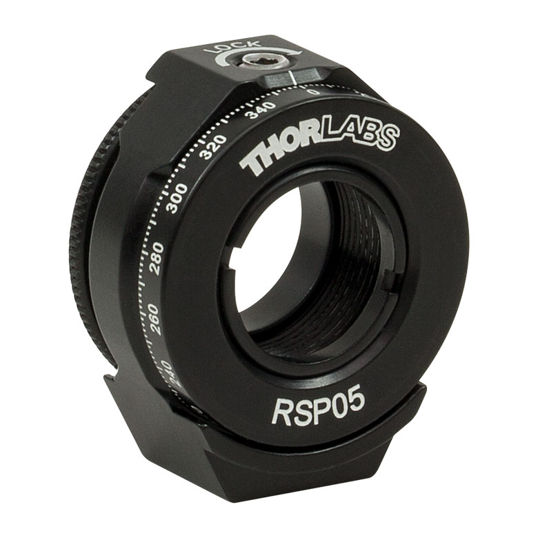
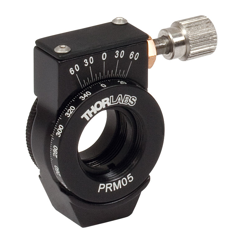
| Item # | MRM05(/M) | RSP05(/M) | CRM05 | PRM05(/M)a | SRM05 | KS05RS | CT104 |
| Click Photo to Enlarge |
 |
 |
 |
 |
 |
 |
 |
| Features | Mini Series | Standard | External SM1 (1.035"-40) Threads |
Micrometer | 16 mm Cage-Compatible | ±4° Kinematic Tip/Tilt Adjustment Plus Rotation | Compatible with CT1 Cage Translator Stage and 1/4" Translation Stagesb |
| Additional Details | |||||||
| Rotation Mounts for Ø1" Optics | ||||||||
|---|---|---|---|---|---|---|---|---|
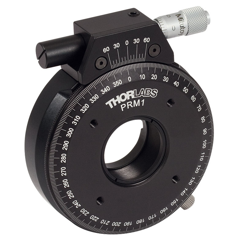
| Item # | RSP1(/M) | LRM1 | RSP1D(/M) | DLM1(/M) | CLR1(/M) | RSP1X15(/M) | RSP1X225(/M) | PRM1(/M)a |
| Click Photo to Enlarge |
 |
 |
 |
 |
 |
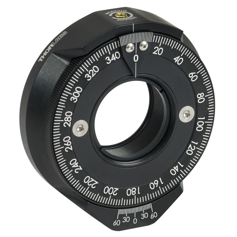 |
|
 |
| Features | Standard | External SM1 (1.035"-40) Threads |
Adjustable Zero | Two Independently Rotating Carriages | Rotates Optic Within Fixed Lens Tube System |
Continuous 360° Rotation or 15° Increments |
Continuous 360° Rotation or 22.5° Increments |
Micrometer |
| Additional Details | ||||||||
| Rotation Mounts for Ø1" Optics | ||||||
|---|---|---|---|---|---|---|
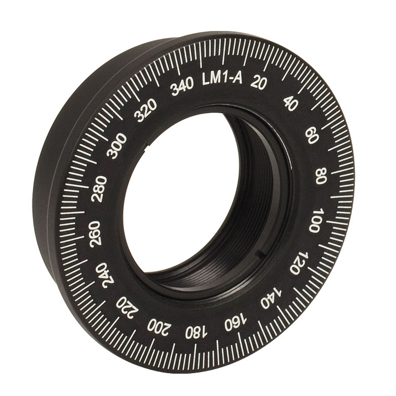
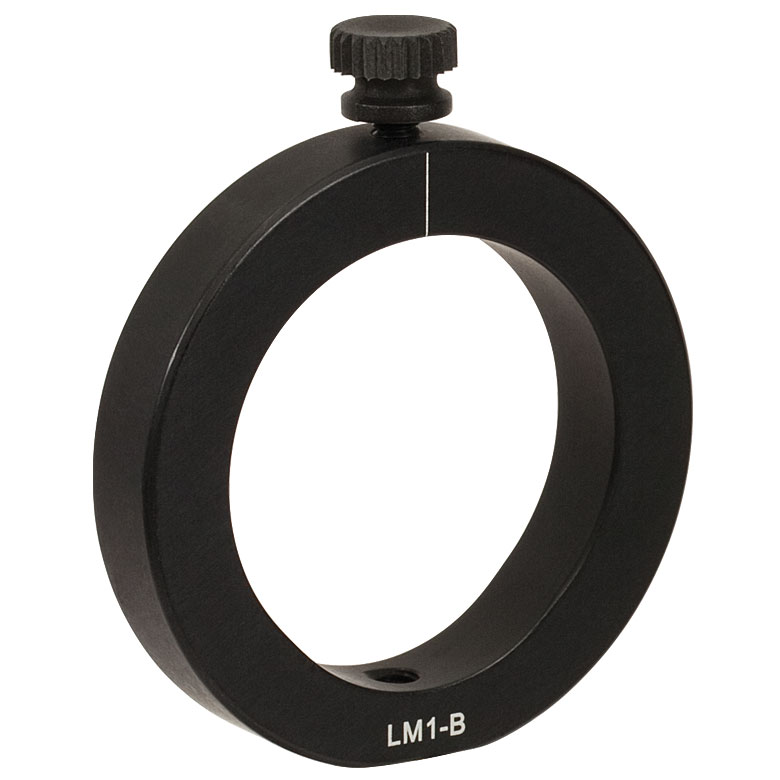
| Item # | LM1-A & LM1-B(/M) |
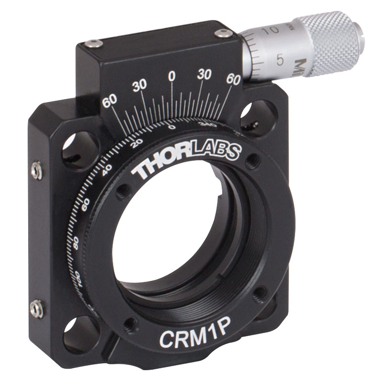
CRM1(/M) | CRM1L(/M) | CRM1P | KS1RS | K6XS |
| Click Photo to Enlarge |
  |
 |
 |
 |
 |
 |
| Features | Optic Carriage Rotates Within Mounting Ring | 30 mm Cage-Compatiblea | 30 mm Cage-Compatible for Thick Opticsa |
30 mm Cage-Compatible with Micrometera |
±4° Kinematic Tip/Tilt Adjustment Plus Rotation | Six-Axis Kinematic Mounta |
| Additional Details | ||||||
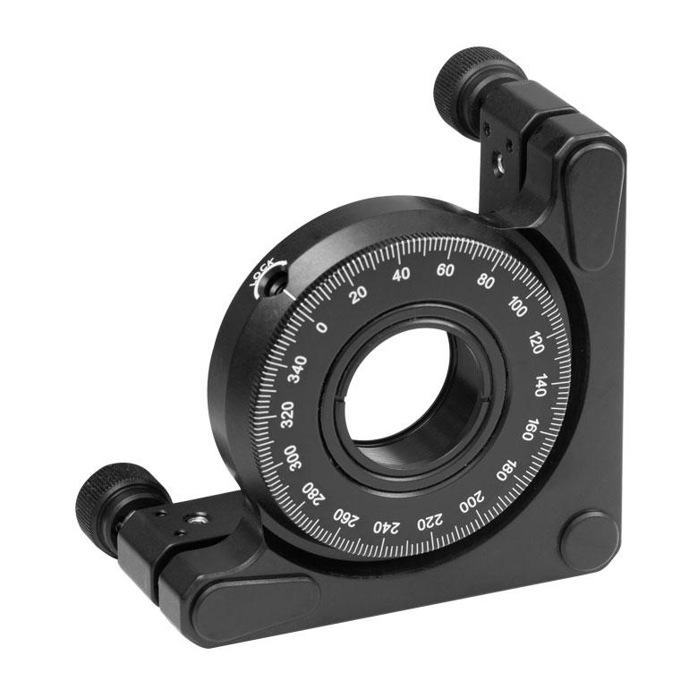
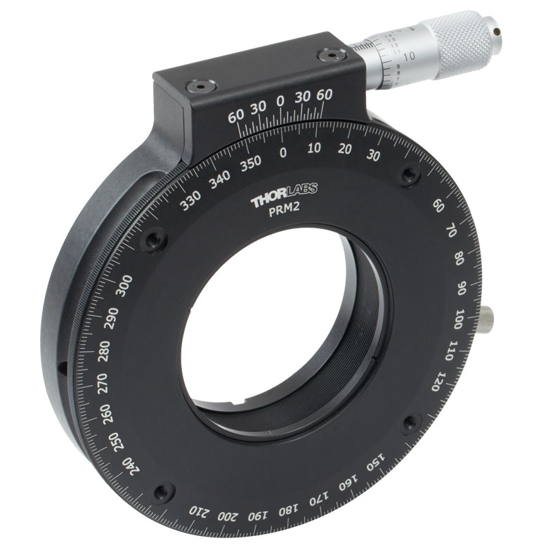
| Rotation Mounts for Ø2" Optics | |||||||
|---|---|---|---|---|---|---|---|
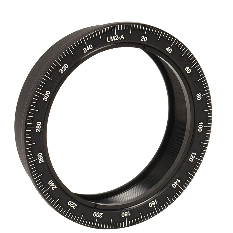
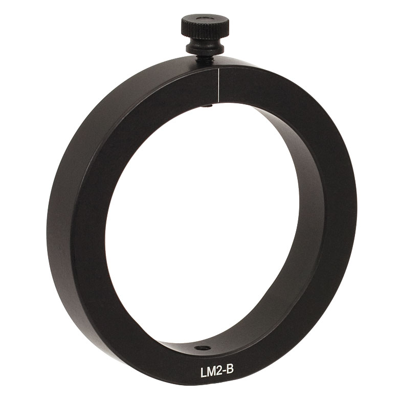
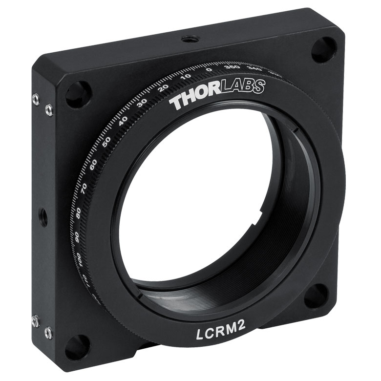
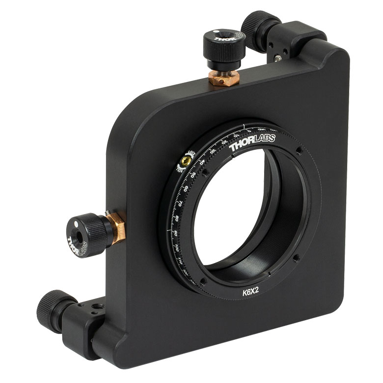
| Item # | RSP2(/M) | RSP2D(/M) | PRM2(/M) | LM2-A & LM2-B(/M) |
LCRM2(/M) | KS2RS | K6X2 |
| Click Photo to Enlarge |  |
 |
 |
  |
 |
 |
 |
| Features | Standard | Adjustable Zero |
Micrometer | Optic Carriage Rotates Within Mounting Ring | 60 mm Cage-Compatible | ±4° Kinematic Tip/Tilt Adjustment Plus Rotation | Six-Axis Kinematic Mount |
| Additional Details | |||||||
Manual Rotation Stages
| Manual Rotation Stages | ||||||
|---|---|---|---|---|---|---|
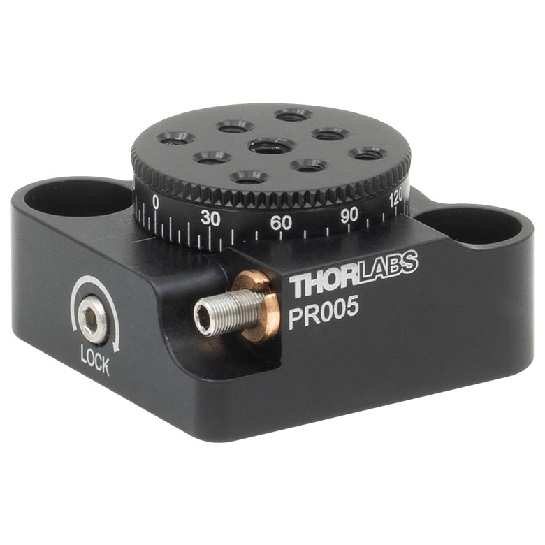
| Item # | RP005(/M) | PR005(/M) | MSRP01(/M) | RP01(/M) | RP03(/M) | QRP02(/M) |
| Click Photo to Enlarge |
 |
 |
 |
 |
 |
 |
| Features | Standard | Two Hard Stops | ||||
| Additional Details | ||||||
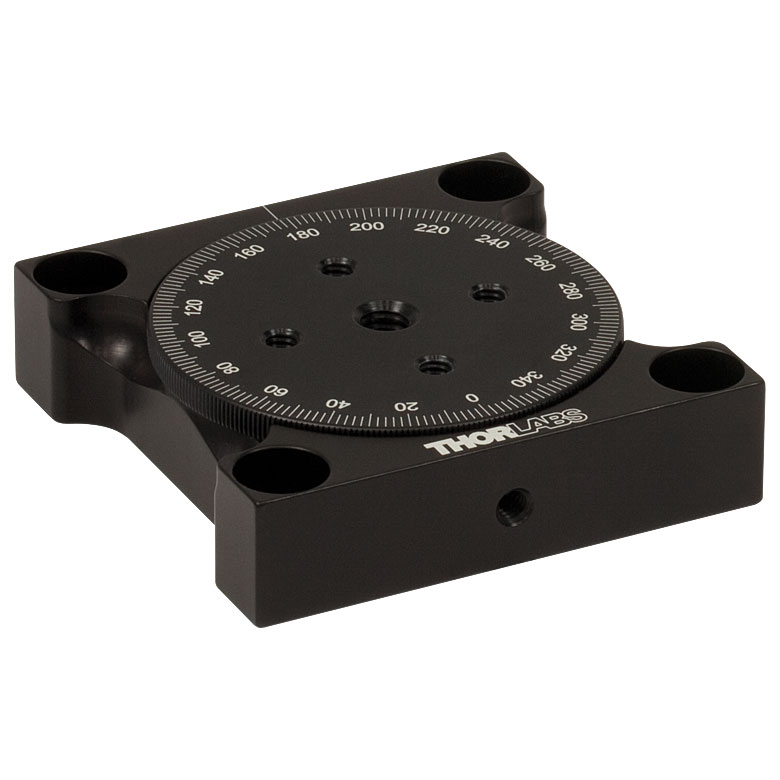
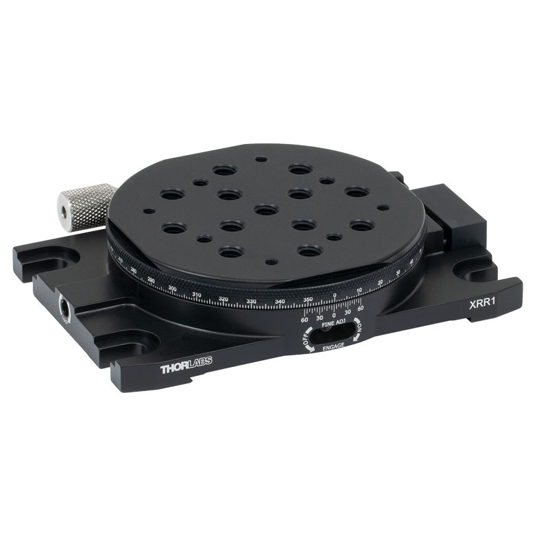
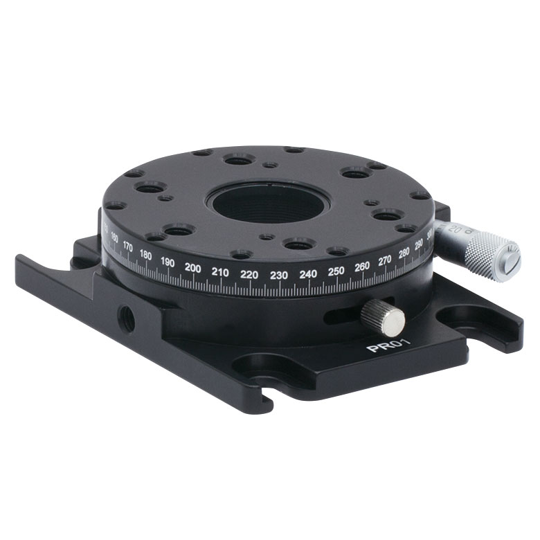
| Manual Rotation Stages | ||||||
|---|---|---|---|---|---|---|
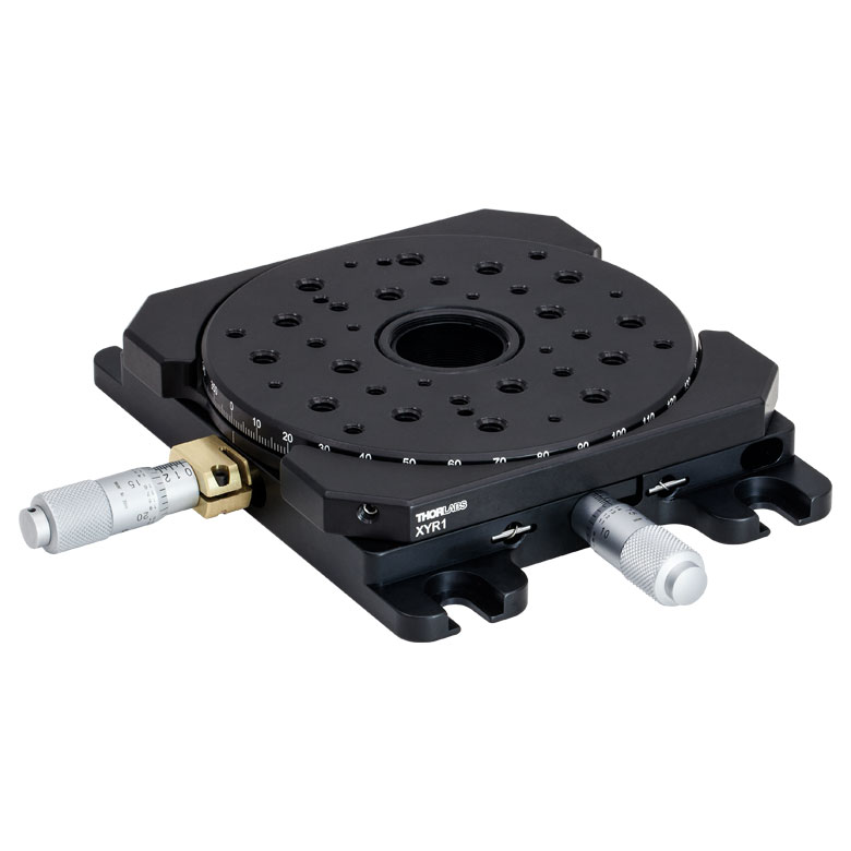
| Item # | XRNR1(/M) | XRR1(/M) | PR01(/M) | CR1(/M) | XYR1(/M) | OCT-XYR1(/M) |
| Click Photo to Enlarge |
 |
 |
 |
 |
 |
 |
| Features | Fine Rotation Adjuster and 2" Wide Dovetail Quick Connect |
Fine Rotation Adjuster and 3" Wide Dovetail Quick Connect |
Fine Rotation Adjuster and SM1-Threaded Central Aperture |
Fine Pitch Worm Gear | Rotation and 1/2" Linear XY Translation | |
| Additional Details | ||||||
Motorized Rotation Mounts and Stages
| Motorized Rotation Mounts and Stages with Central Clear Apertures | |||||||
|---|---|---|---|---|---|---|---|
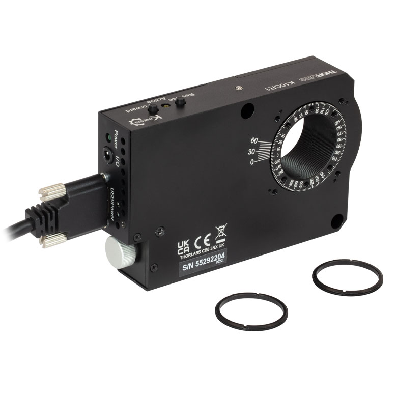
| Item # | DDR25(/M) | PDR1(/M) | K10CR1(/M) | PRM1Z8(/M)a | DDR100(/M) | ELL14 | HDR50(/M) |
| Click Photo to Enlarge |
 |
 |
 |
 |
 |
 |
 |
| Features | Compatible with SM05 Lens Tubes, 16 mm Cage System, 30 mm Cage System |
Compatible with SM05 Lens Tubes, 30 mm Cage System, PD1(/M) Linear Stages |
Compatible with SM1 Lens Tubes & 30 mm Cage System |
Compatible with SM1 Lens Tubes, 16 mm Cage System, 30 mm Cage System |
Compatible with SM1 Lens Tubes, Open Frame Design for OEM Applications |
Compatible with SM2 Lens Tubes |
|
| Additional Details | |||||||
| Motorized Rotation Mounts and Stages with Tapped Platforms | ||
|---|---|---|
| Item # | PRMTZ8(/M)a | ELL18(/M)b |
| Click Photo to Enlarge |
 |
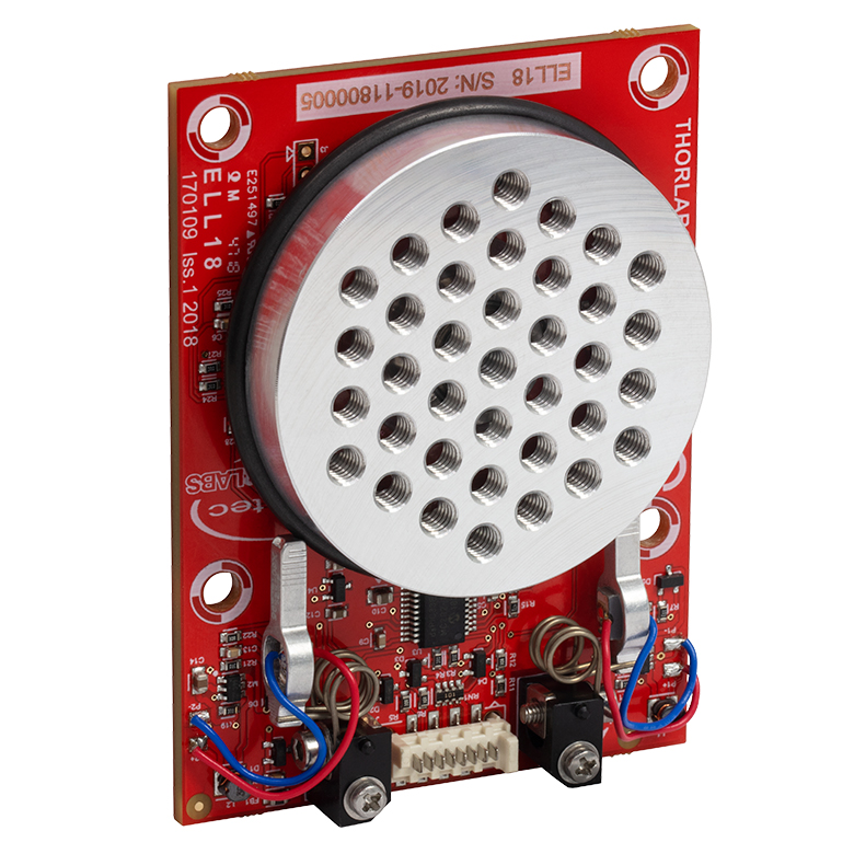 |
| Features | Tapped Mounting Platform for Mounting Prisms or Other Optics | Tapped Mounting Platform, Open Frame Design for OEM Applications |
| Additional Details | ||

 Zoom
Zoom
Click to Enlarge
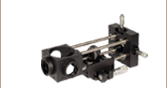
The motors' aluminum tips contact the black plastic track encircling the rotation mount. This track should not be touched to prevent debris and oil building up on the track.
- Ideal for OEM Evaluation Testing
- Easily Integrate into a Setup
- Operate using Manual and/or Computer Control
- Included Power Supply is Required for Powering the Mount
The Rotation Mount Bundle is a complete package that includes the ELL14 rotation mount. The ELL14K package facilitates quick integration of the rotation mount into laboratory setups and other experimental applications. It also provides a convenient means to evaluate incorporating this technology into OEM applications.
The tips of both motor housings are in firm contact with the plastic track encircling the rotation mount, as can be seen in the image to the right. The motors are installed with opposite orientations and clockwise (and counterclockwise) rotation occurs when one motor pushes the track forward while the other pulls it backward.
| Included in the ELL14K Bundle | |
|---|---|
| ELL14 Rotation Mount | 5 V Power Supply with Region-Specific Power Adapter |
| Interface Board | 8-Conductor 28 AWG Ribbon Cable |
| USB Cable | PC-Based Software for Download |

 Zoom
ZoomClick to Enlarge
Features of the Rotation mount
This Rotation Mount is offered to meet the needs of applications whose designs require multiple networked Elliptec resonant motor products. It possesses an SM1-threaded mount for holding Ø1" optics. Details describing the dimensions, including the spacing of mounting holes, and other specifications of the mount are given in the Specs tab. Please contact us to discuss customizing the rotation mount.
The PCB of the rotation mount incorporates a male 8-pin Picoflex® connector (header). Each ELL14 mount ships with the female 8-pin Picoflex® connector (receptacle) that mates with the connector (header) on the board.

 Zoom
Zoom| Specifications | ||
|---|---|---|
| Item # | ELLB | |
| Voltage Rating | 4.5 to 5.5 V | |
| Typical Current Consumption Per Module | Movement | 800 mA |
| Standby | 50 mA | |
| Maximum Board Current | 4.0 A | |
| Operating Temperature Range | 15 to 40 °C | |
| Ribbon Cable Length (4 Included) | 250 mm | |
| Maximum Supported Ribbon Cable Length |
500 mm | |
| Dimensions | 65.0 mm x 32.0 mm x 12.5 mm (2.56" x 1.26" x 0.49") |
|
| Weight | 11 g (0.02 lbs) | |

Click to Enlarge
A single bus distributor can be used to control up to four Elliptec devices. The bus can be connected to a PC using the interface board provided with the bundles sold above. Note that the bus is then controlled by the Elliptec software and that the buttons on the interface board are disabled.
- Control and Power up to Four Elliptec™ Devices with One Bus
- Daisy Chain Bus Boards to Control up to 16 Elliptec Devices
- Controlled Remotely Using Elliptec System Software (See Software Tab Above)
- Connect to PC Using USB Interface Board Included with Elliptec Bundles
- Five Jumpers and Four 8-Conductor 28 AWG Ribbon Cables Included
- Compatible with Raspberry Pi® and Arduino® Boards
The ELLB Bus Distributor connects up to four Elliptec™ devices. Connected devices can be controlled with or without the interface board included with the above bundles. When using the interface board, each connected device is controlled remotely by a PC running the Elliptec software package. The interface board connects to the bus's input port labeled REMOTE; once connected, the interface board's buttons are disabled. For control without using the interface board, see the Pin Diagrams tab for custom connections.
Multiple ELLB Bus Distributors can be daisy chained to control and power up to 16 Elliptec devices; simply connect one of the four MODULE outputs to the second board's REMOTE input. Indicator LEDs are provided to show which device is active. The communications protocol manual describes how to use the software to individually address each connected device. A link to download the software and accompanying documentation can be found in the Software tab.
The bus includes a Ø6.3 mm power connector that supports a 5 V supply with a maximum current of 4 A. As more devices are connected, simultaneous control of the units will require more current to be provided by the power supply; please see the Specs tab for the amount of current drawn by each Ellitpec device. Power supply options provided by Thorlabs include the TPS101 5 V, 2 A power supply and the 5 V, 1 A supply included with the above bundles. Depending on the current draw of the Elliptec devices connected, these supplies provides enough current to power two devices simultaneously.
Fourteen control pins, detailed in the image to the right, are included for additional functionality. Four pairs of pins are each shorted with a jumper that, when in place, enables the Elliptec software to receive feedback from connected Elliptec devices. The pair of pins labeled LED is shorted with a jumper that, when removed, will disable the indicator LEDs. The 5V and GND allow an optional, user-provided 5 V, 2 A power supply to be used in place of a source connected to the Ø6.3 mm power connector. The RX and TX pins can be used to control the bus with a Raspberry Pi® or Arduino® board, respectively, instead of the Elliptec interface board.
The board is mounted using the Ø3.5 mm through holes provided in each corner. Four 8-conductor, 28 AWG ribbon cables are included.
| Compatible Elliptec Devices | ||||
|---|---|---|---|---|
|
|
|
|
|
| Multi-Position Sliders | 28 mm Linear Stage | 60 mm Linear Stage | Rotation Stage | Rotation Mount |