 Products Home
SAF Gain Chips, 1450 nm Center Wavelength

- InP Gain Chip on Submount or Submount with Heatsink
- Ultra-Low Reflectance at Angled Facet
- Custom Coatings Available
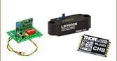
Actual Size Compared
to US One Cent Coin
SAF1093C
Chip on Submount
SAF1093H
Chip on Submount
with Heatsink


Please Wait
| Parameter | Min | Typ | Max |
|---|---|---|---|
| Operating Current (IOP) | - | 500 mA | 800 mA |
| Center Wavelength | 1420 nm | 1450 nm | 1480 nm |
| ASE Power @ IOP | 10 mW | 20 mW | - |
| Peak Gain @ IOP | - | 33 dB | - |
| Optical Bandwidth | 80 nm | 95 nm | - |
| Gain Ripple (RMS) @ IOP Res. BW = 0.1 nm |
- | 0.3 dB | 1 dB |
| Angled Facet Reflectivity | - | 0.005% | 0.01% |
| Normal Facet Reflectivity | - | 90% | - |
| Forward Voltage | - | 1.4 V | 1.8 V |
| Chip Length | - | 1.5 mm | - |
| Waveguide Refractive Index | - | 3.2 | - |
| Lateral Beam Exit Angle | - | 26.5° | - |
| Transverse Beam Divergence (FWHM) |
- | 30° | - |
| Lateral Beam Divergence (FWHM) |
- | 15° | - |
Features
- Broad Tuning Range
- High Output Power
- Ultra-Low Angled Facet Reflectance: 0.005% (Typ)
- Gain Medium for Narrow Linewidth Fiber Bragg Grating Lasers
- Gain Medium for Widely Tunable External Cavity Semiconductor Lasers
Single Angled Facet (SAF) gain chips use a geometric technique to further reduce the reflection on one end of the chip by curving the ridge waveguide so that it is not normally incident to the chip facet. This, in combination with an AR coating on that facet, virtually eliminates back reflections that can create unwanted feedback into the laser cavity. As a result, SAF gain chips are superior to standard gain chips when used in Extended Cavity Lasers (ECLs), particularly tunable ECLs, since any residual reflection from the AR-coated Fabry-Perot (FP) gain chip facet often limits the stability, output power, and spectral quality of the laser.
Our 1450 nm SAF gain chip is available in two configurations. The SAF1093C chip is offered on a submount, while the SAF1093H is provided on the same submount with a heatsink and connected cathode and anode leads.
Sample Results of an SAF1093 Used in a Basic Littrow Configuration

For more information on using a SAF gain chip in an external cavity laser see the online External Cavity Diode Laser Tutorial.


Click to Enlarge
Diagram of the Anode and Cathode Pins of the SAF1093C

Click to Enlarge
Diagram of the Anode and Cathode Pins of the SAF1093H
| Posted Comments: | |
barry.luther-davies
(posted 2015-04-14 11:47:27.227) What are the polarisation properties of these chips? Does not seem to be specified anywhere. jlow
(posted 2015-04-16 08:39:46.0) Response from Jeremy at Thorlabs: The SAF chips are TE-polarized. Typically, the polarization extinction ratio is >18dB. jjurado
(posted 2011-08-08 11:01:00.0) Response from Javier at Thorlabs to clarafly: The width and height of the active region of the SAF1093 chip is ~3um and ~1um, respectively. clarafly
(posted 2011-08-05 13:58:00.0) Can you provide the information about the width and height of the active region in SAF1093x? Thanks. |